Method for performing ultrasonic testing

a technology of ultrasonic testing and ultrasonic testing, which is applied in the direction of instruments, heat measurement, thermometer details, etc., can solve the problems of limiting the ability of ultrasonic testing systems in certain applications, the required degree of thickness measurement accuracy is extremely high, and the complexity of ultrasonic testing systems is increased. , the cost of installing and maintaining such a system is increased

Active Publication Date: 2011-04-21
GE INSPECTION TECH LP
View PDF9 Cites 20 Cited by
  • Summary
  • Abstract
  • Description
  • Claims
  • Application Information

AI Technical Summary

Problems solved by technology

This limits the ability of the ultrasonic testing system in certain applications, such as determining pipe corrosion rates, as the required degree of accuracy in the thickness measurements is ext

Method used


Image

  • Method for performing ultrasonic testing
  • Method for performing ultrasonic testing
  • Method for performing ultrasonic testing

Examples


Embodiment Construction

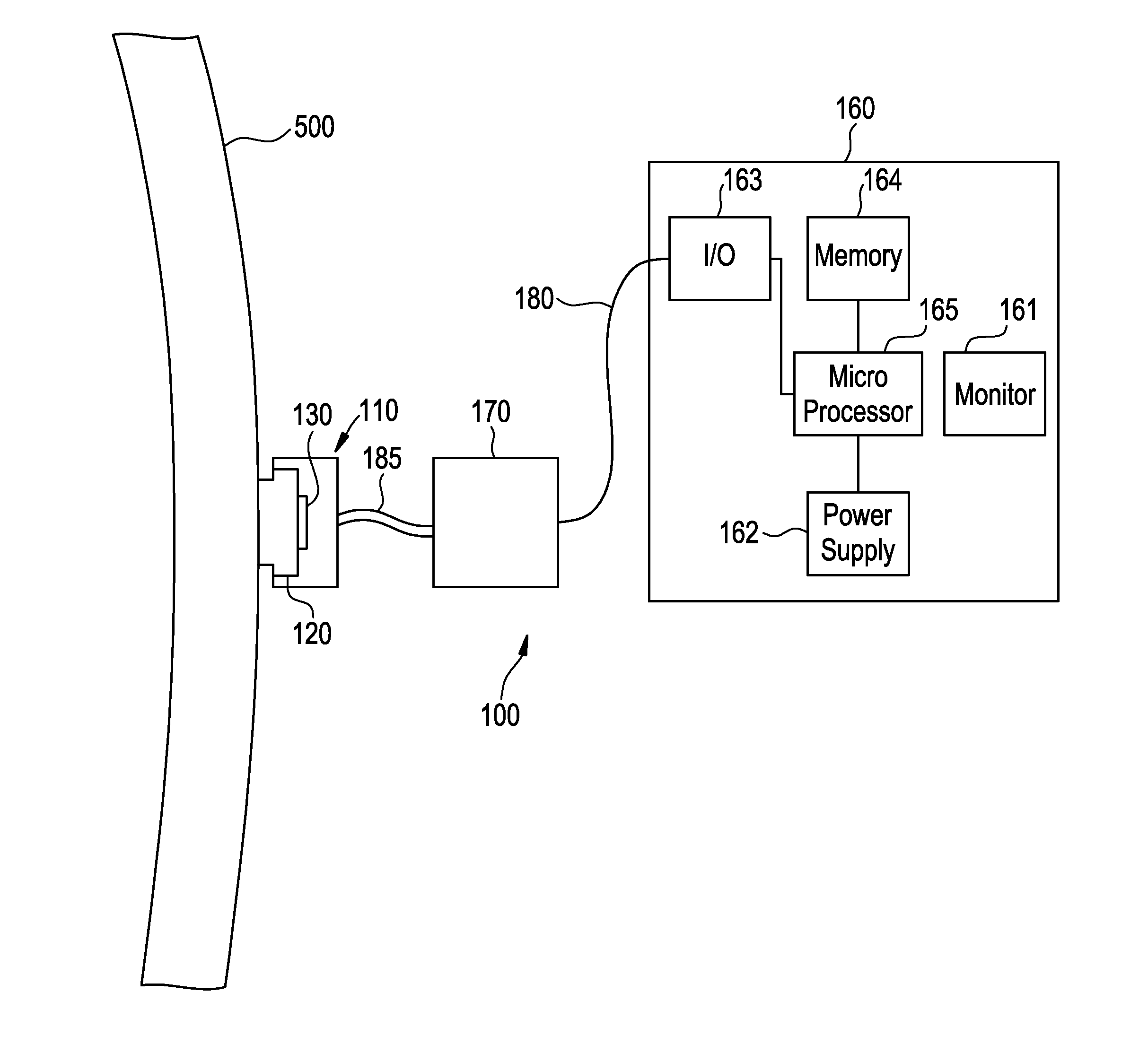
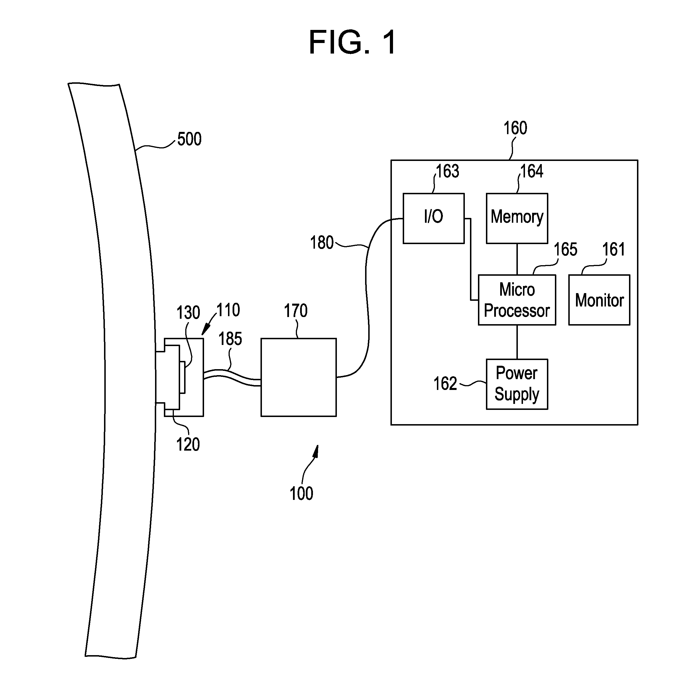
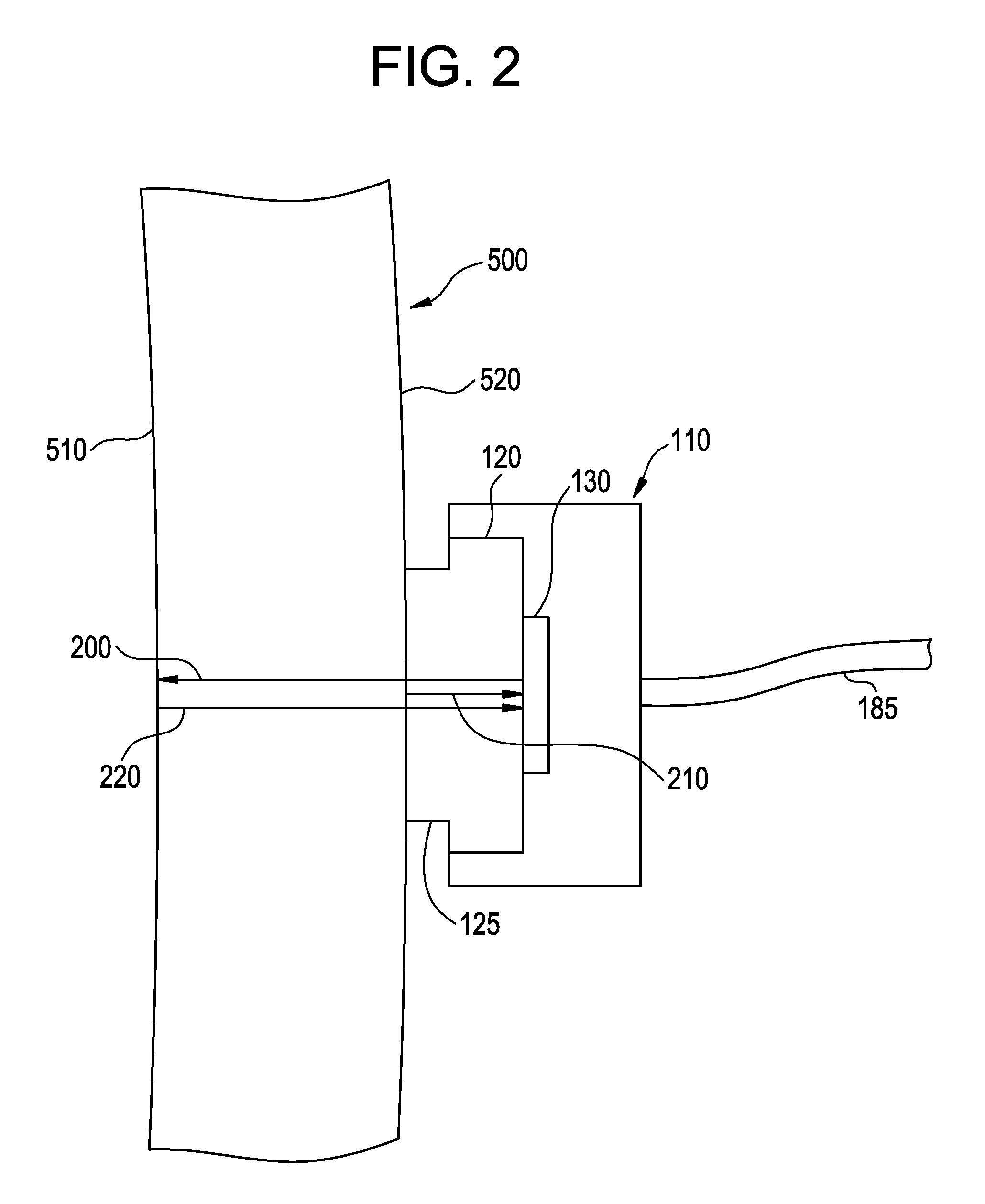
[0014]FIG. 1 is a block diagram of an ultrasonic testing system 100 in combination with a test object 500. In one embodiment, ultrasonic testing system 100 can comprise an ultrasonic transducer 110 that can be attached to a delay line 120. Transducer 110 can include an ultrasonic element 130 for transmitting and receiving ultrasonic sound pulses. In some embodiments, the delay 120 can be made integral to the transducer 110. In other embodiments, the delay line 120 can be separately attached to the transducer 110. Transducer 110 and delay 120 can be mechanically attached to the test object 500 using various means (e.g., U-bolts or clamps) to ensure a secure thermocoupling between the delay 120 and the test object 500. Over time, the temperature of the delay line 120 will be the same as that of the test object 500. The delay line 120 can be made from a variety of materials including but not limited to stainless steel, titanium, ceramic, or various alloys, such as INCONEL® available fr...


PUM


Abstract

A method for performing ultrasonic testing comprising, in one embodiment, the steps of firing an ultrasonic transducer to generate an ultrasonic pulse that passes through a delay line, measuring a delay echo time of flight, and determining the temperature of the delay line using the delay echo time of flight, thereby eliminating the need for additional temperature measuring devices. Other embodiments further comprise the step of using the temperature of the delay line to determine the temperature of a test object, and using the temperature of the test object to determine a thickness of the test object that is compensated for thermal expansion and temperature dependent ultrasonic velocity.

Description

BACKGROUND OF THE INVENTION[0001]This invention relates generally to nondestructive testing, and more particularly to a method for determining the temperature of a test object by ultrasonically measuring the temperature of an ultrasonic delay line in close thermal contact with the test object. Furthermore, this invention relates to the temperature compensation of ultrasonic test measurements using the aforementioned ultrasonic temperature measurement of the test object.[0002]Nondestructive testing devices can be used to inspect test objects to identify and analyze flaws and defects in the objects both during and after an inspection. Nondestructive testing allows an operator to place a probe at or near the surface of the test object in order to perform testing of both the object surface and underlying structure. Nondestructive testing can be particularly useful in some industries, e.g., aerospace, power generation, and oil and gas recovery and refining, where object testing must take...

Claims


Application Information

Patent Timeline
IPC IPC(8): G01K11/22
CPCG01K11/22G01B17/02G01N29/024G01N29/043G01N29/2468G01N29/326G01N2291/011G01N2291/02854G01N2291/02881
Inventor CUFFE, JOHN MICHAELBARSHINGER, JAMESFAN, YING
Owner GE INSPECTION TECH LP
Why Eureka
Try Eureka