Low frequency broad band ultrasonic transducers

a broad band, ultrasonic transducer technology, applied in the field of ultrasonic transducers, can solve the problems of increasing the size of the current design, unable to achieve bandwidth and ringdown goals, and the current design is unsuitable and/or unusable in down-hole cbe applications, and achieves the effect of a broader frequency rang

Inactive Publication Date: 2013-12-26
PIEZO TECH
View PDF7 Cites 19 Cited by
  • Summary
  • Abstract
  • Description
  • Claims
  • Application Information

AI Technical Summary

Benefits of technology

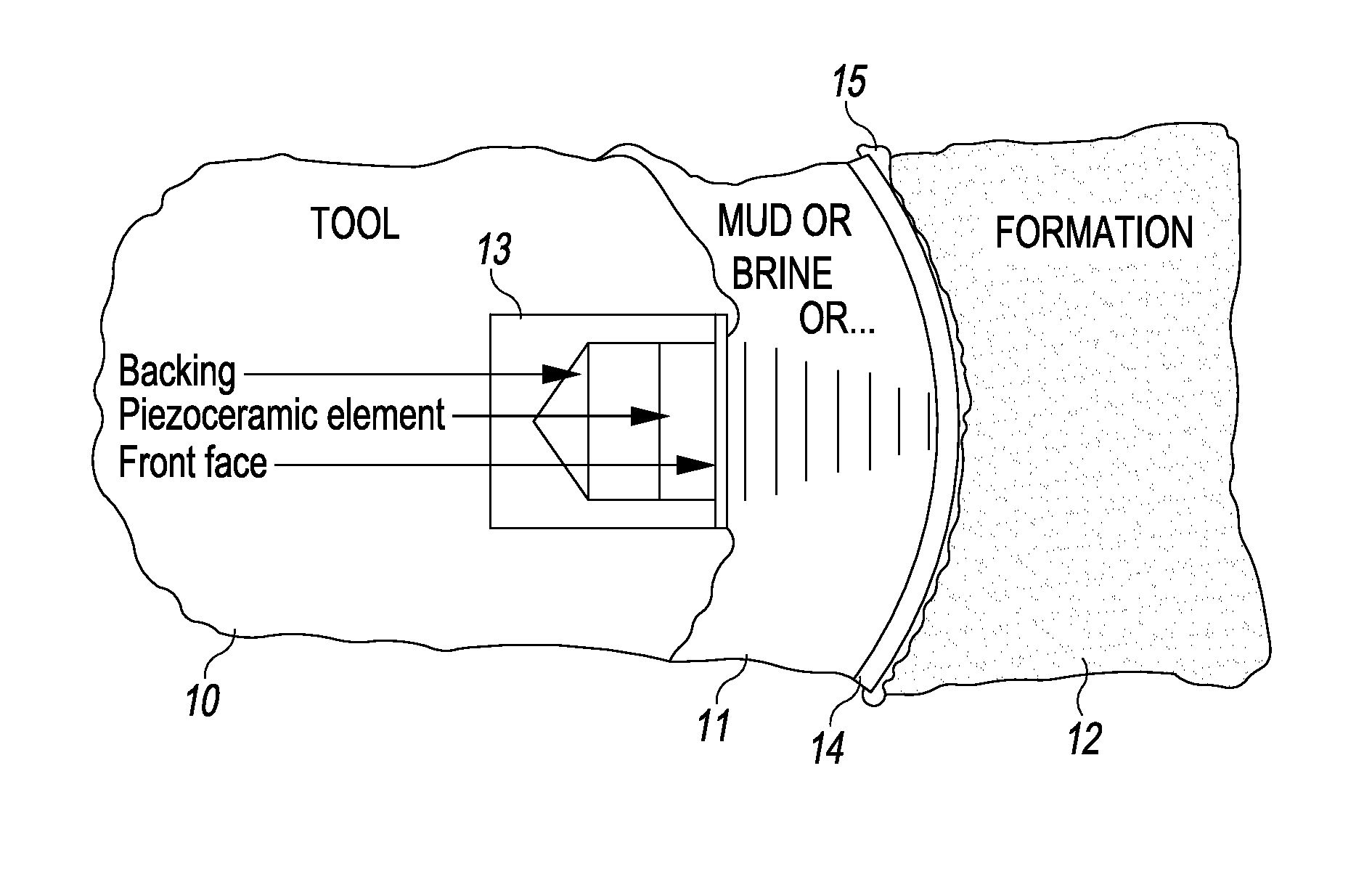
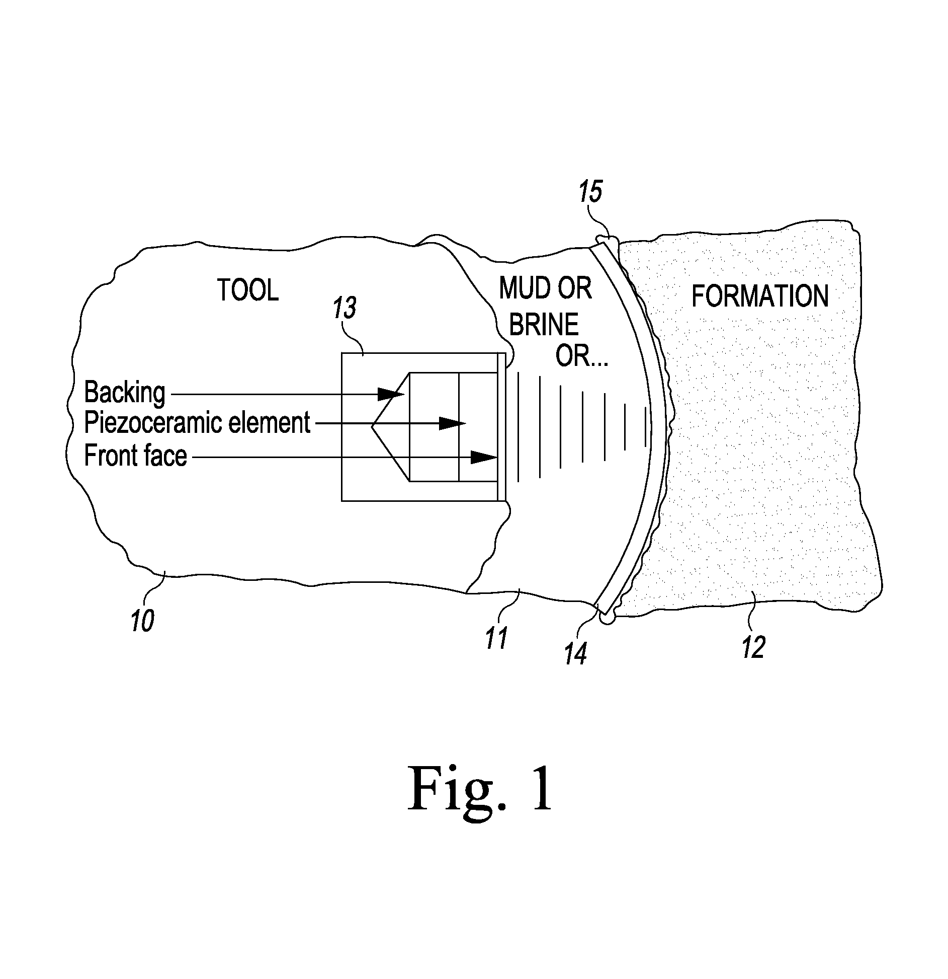
[0015]In another form, the present low frequency pulse-echo ultrasonic transducer comprises an assembly having the present transducer stack disposed on an acoustic dampening or attenuating backing and a front face element. The front face element is preferably, but not necessarily, a ¼ wavelength (¼λ) PEEK (polyetheretherketone) or titanium structure.
[0016]In another form, the present low frequency pulse-echo ultrasonic transducer comprises a composite made from a lead metaniobate (PmN, PN, LM, PbNb or other label). The composite is characterized by an array of piezoceramic posts (units) set into a low acoustic impedance matrix. The piezoceramic units can be made from a lead metaniobate known as “K-81” and “K-91” as provided by the assignee, Piezo Technologies of Indianapolis, Ind.
[0017]In yet another form, the present low frequency pulse-echo ultrasonic transducer comprises a composite stack, preferably, but not necessarily, made from a lead metaniobate. Each unit of the composite stack consists of a transducer stack as described above.
[0018]In still another form, the present low frequency pulse-echo ultrasonic transducer comprises a composite stack, preferably, but not necessarily, made from a lead metaniobate, wherein multiple drive elements allow driving individual elements at different times. The multiple drive elements can be phase delayed relative to one another to provide a broader frequency range.
[0019]The present low frequency pulse-echo transducers may be used in a variety of applications, including medical, remote sensing, and wells for recovering fossil fuels.

Problems solved by technology

A problem with low frequency transducers for CBE applications however is their size since down-hole tools only have so much room for the ultrasonic transducer assembly.
Every change associated with dropping the operating frequency of the ultrasonic transducer makes achieving bandwidth and ringdown goals more difficult.
Therefore, while it would be advantageous to have a low frequency (i.e. ˜100 kHz) ultrasonic transducer for use in CBE and other applications, the aforementioned problems with respect to low frequency (i.e. 100 kHz) ultrasonic transducers makes current designs unsuitable and / or unusable in down-hole CBE applications.
As the ability of the backing to absorb energy from the transducer decreases (due to limited space in a downhole tool for a transducer assembly), loss in the transducer must be increased to meet bandwidth goals.

Method used


Image

  • Low frequency broad band ultrasonic transducers
  • Low frequency broad band ultrasonic transducers
  • Low frequency broad band ultrasonic transducers

Examples


Embodiment Construction

[0042]Referring to FIG. 5, there is depicted a general illustration of a low-frequency pulse-echo acoustic (e.g. ultrasonic) transducer stack, generally designated 50, fashioned in accordance with the present principles. The acoustic transducer stack 50 is characterized by alternating layers of an acoustic (e.g. ultrasonic or piezoceramic) element and an ultrasonic dampening or attenuating element. In FIG. 5, the acoustic transducer stack 50 has a first piezoceramic element 51, a first acoustic dampening element 52 situated on the first piezoceramic element 51, a second piezoceramic element 53 situated on the first acoustic dampening element 52, a second acoustic dampening element situated on the second piezoceramic element 53, and a third piezoceramic element 55 situated on the second acoustic dampening element 52. The acoustic damping elements 52, 54 are preferably acoustic impedance matched to the piezoceramic elements 51, 53, 55 in order to reduce the Q of the transducer stack. ...


PUM


Abstract

Low frequency pulse-echo ultrasonic transducers are provided especially suited for use in downhole cement bond evaluation, but usable for various applications. One frequency pulse-echo ultrasonic transducer comprises a transducer stack having alternating layers of a piezoceramic element and an ultrasonic attenuating element that is preferably acoustic impedance matched to the piezoceramic elements in order to reduce the Q of the transducer stack. Another low frequency pulse-echo ultrasonic transducer comprises an assembly having the present transducer stack disposed on an acoustic attenuating backing and a front face. Yet another low frequency pulse-echo ultrasonic transducer comprises a transducer composite made from a lead metaniobate. Still another frequency pulse-echo ultrasonic transducer comprises a composite stack. A further low frequency pulse-echo ultrasonic transducer comprises a composite stack, wherein multiple drive elements allow driving individual elements at different times. The transducers may be driven in a multiple-pulse time delayed manner.

Description

CROSS-REFERENCE TO RELATED APPLICATIONS[0001]This U.S. non-provisional patent application claims the benefit of and priority to U.S. provisional patent application Ser. No. 61 / 641,004 filed May 1, 2012 entitled “Low Frequency Broad Band Ultrasonic Transducers”, and to U.S. provisional patent application Ser. No. 61 / 673,823 filed Jul. 20, 2012 entitled “Low Frequency Broad Band Ultrasonic Transducers”, the entire contents of each of which is specifically incorporated herein by reference.FIELD OF THE INVENTION[0002]The present invention relates to the field of ultrasonic transducers and, more particularly, to low frequency pulse-echo ultrasonic transducers. Such transducers can be employed, for example, in well cement bond evaluation applications.BACKGROUND[0003]When forming a well, such as an oil or natural gas well, a hole is drilled in the earth using an earth-penetrating drill bit situated at an end of one or more drilling tools which, in turn, are disposed at the end of numerous ...

Claims


Application Information

Patent Timeline
Patent Type & Authority Applications(United States)
IPC IPC(8): H01L41/053H01L41/04
CPCH01L41/053H01L41/04B06B1/0685G10K11/002G01S7/521E21B47/005H10N30/88H10N30/80
Inventor LAUTZENHISER, FRANSMOLZ, ERICMATAM, MAHESH
Owner PIEZO TECH
Why Eureka
Try Eureka