
Belt feed mechanism for mil-spec linked ammo

a technology of mil-spec linked ammo and belt feed mechanism, which is applied in the field of belt feed mechanism for mil-spec linked ammo, can solve the problems of substantial lower likelihood of jams, and achieve the effect of minimizing torsional stresses

Inactive Publication Date: 2016-11-08
SLIDE FIRE SOLUTIONS
View PDF45 Cites 3 Cited by
  • Summary
  • Abstract
  • Description
  • Claims
  • Application Information

AI Technical Summary

Benefits of technology

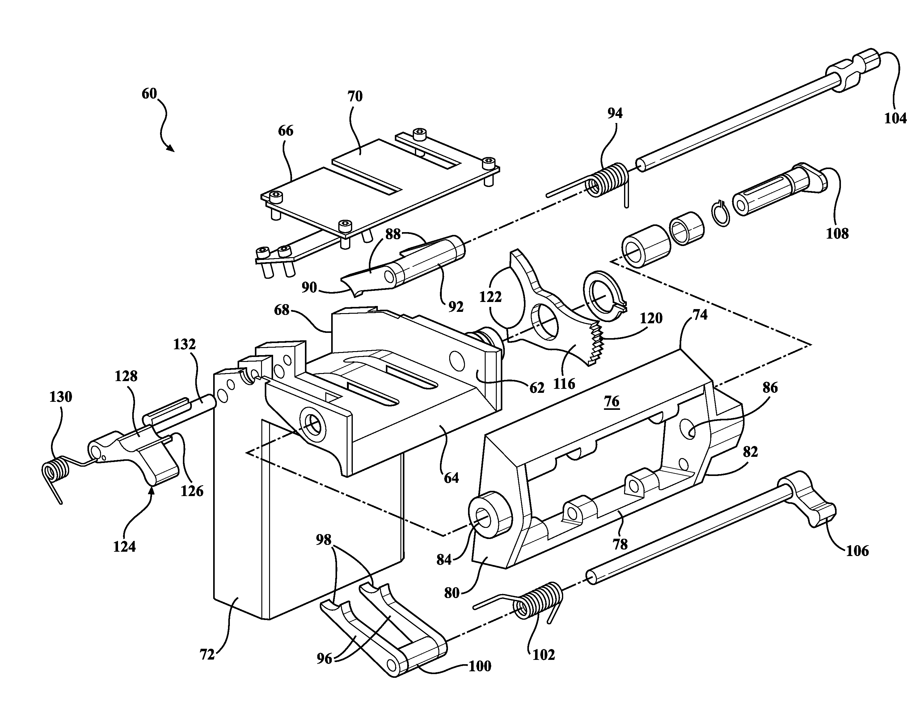
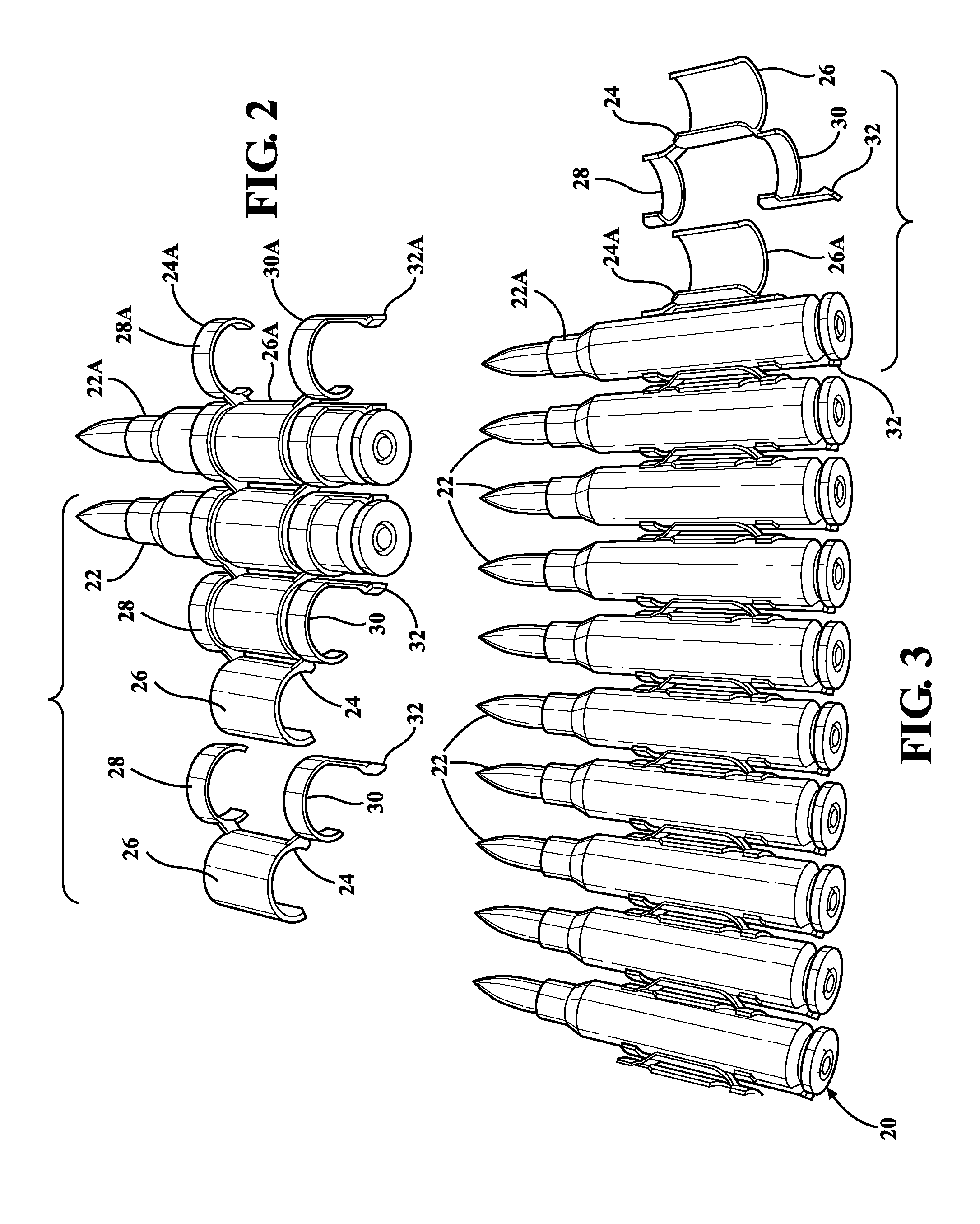
[0016]A feeding device for ammunition cartridges connected together in an elongated belt by separable links wherein the firearm individually separates a lead cartridge and a lead link from the remainder of the ammunition belt prior to chambering the lead cartridge in a breach. The device comprises a feed chute defining a transverse feed path configured to receive the ammunition belt with lead cartridge and connected lead link through an inlet. The feed chute further includes a central stripping station disposed along the transverse feed path. A first outlet is provided for discharging the lead cartridge after it has been separated from the lead link. A second outlet is provided for discharging the lead link after it has been separated from the lead cartridge. A transfer mechanism is operatively associated with the feed chute for sequentially moving the lead cartridge and its connected lead link into the central stripping station. The improvement comprises a sheering lip disposed in the central stripping station. The sheering lip is configured to engage a portion of the lead link directly below the lead cartridge to resist separating forces when the lead cartridge is pushed through the first outlet. Placement of the sheering lip directly below the lead cartridge minimizes the torsional stresses that are induced into the ammunition belt by the harsh stripping forces.
[0017]The present invention enables a lower-receiver style feeding device to achieve the advantages of the prior art upper-receiver style feeding devices while eliminating the traditional disadvantages of the prior art lower-receiver style feeding devices. The sheering lip of this invention is disposed to engage the lead link directly below the lead cartridge when the lead cartridge is moved into the central stripping station. By locating the sheering lip directly below the lead cartridge, forces imposed on the lead cartridge during the Feeding and Chambering stages of the firing cycle are resisted in such a way that torsional stresses are minimized. As a result of reduced torsional forces, the cartridges push through their links more easily. Reduced torsional forces also means that the cartridges receive less abrasion and plastic deformation, thus making them better suited for re-loading. The sheering lip feature also results in a substantially lower likelihood of jams due to the reduced push-through resistance.

Problems solved by technology

The sheering lip feature also results in a substantially lower likelihood of jams due to the reduced push-through resistance.

Method used


Image

  • Belt feed mechanism for mil-spec linked ammo
  • Belt feed mechanism for mil-spec linked ammo
  • Belt feed mechanism for mil-spec linked ammo

Examples


Embodiment Construction

[0038]The principles of this invention are adaptable to many different makes and models of firearms. One embodiment of the invention is configured specifically for use with an AR-15 style firearm, like that generally shown at 40 in FIGS. 4 and 5. The AR-15 platform is used herein for illustrative purposes only; it is to be understood that the invention may be practiced with other makes and models of firearms given corresponding modifications that will be apparent to an ordinarily skilled gunsmith.

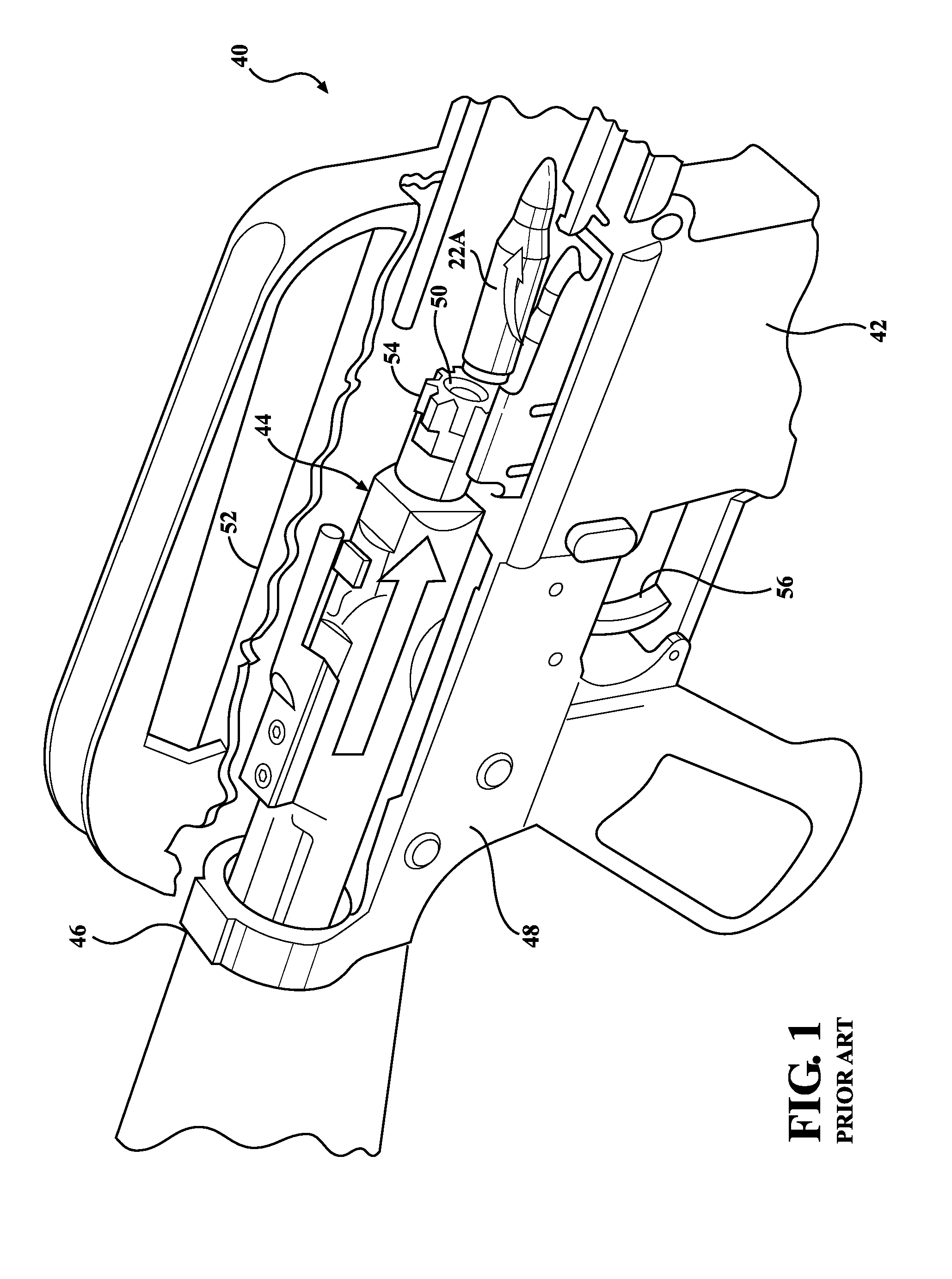
[0039]The firing cycle of a typical magazine-fed AR-15 firearm 40 is described briefly in order to provide context for the exemplary belt-fed AR-platform application of this invention. After a loaded magazine (not shown) has been inserted into the magazine well 42 of the firearm 40, the eight cycles of functioning include: Feeding, Chambering, Locking, Firing, Unlocking, Extracting, Ejecting, and Cocking.

[0040]The Feeding process. As the bolt-carrier group 44 moves rearward, it engages the ...


PUM


Abstract

A lower-receiver type feeding device for belted ammunition cartridges. A lead cartridge of the belt is separated from its lead link at a central stripping station. A rocker-type transfer mechanism sequentially moves cartridges with connected link toward the central stripping station. The transfer mechanism is driven through a cam interface with the bolt-carrier group. A sheering lip is disposed at the central stripping station to engage the lead link directly below the lead cartridge and resist stripping forces when the lead cartridge is pushed through a first outlet for chambering. A mag well post slides into a magazine well of the firearm. A bolt catch extension is pivotally carried on the right pivot shaft to remotely activate the bolt catch. An end-of-link stop is joined to the end of the ammunition belt. The end-of-link stop comprised a dummy cartridge having a longitudinally extending groove.

Description

CROSS REFERENCE TO RELATED APPLICATIONS[0001]This application claims priority to Provisional Patent Application No. 61 / 726,789 filed Nov. 15, 2012, the entire disclosure of which is hereby incorporated by reference and relied upon.BACKGROUND OF THE INVENTION[0002]1. Field of the Invention[0003]The invention relates generally to an ammunition feeding device, and more particularly to such a device for feeding linked ammunition in timed sequence to the firing cycle of a self-loading firearm.[0004]2. Description of Related Art[0005]Firearms require a supply of ammunition. Small arms, including hand-carried rifles and pistols, often carry a small cache of ammunition in a magazine. Magazines are typically configured with an internal spring that helps move the top or lead cartridge stored in the magazine into a position where it may be loaded into the chamber by the action of the firearm. Many magazines hold between about 5-30 cartridges. Even when a magazine is configured to hold more tha...

Claims


Application Information

Patent Timeline
Patent Type & Authority Patents(United States)
IPC IPC(8): F41A5/00G06Q50/00F41A9/29H04L29/08
CPCF41A9/29G06Q50/01H04L67/22H04L67/306F41A9/33H04L67/535
Inventor DELURY, GEORGECOTTLE, JEREMIAH
Owner SLIDE FIRE SOLUTIONS
Learn More