Rail-type vacuum fixer

Inactive Publication Date: 2016-11-15
GOODSENSE
View PDF21 Cites 10 Cited by
  • Summary
  • Abstract
  • Description
  • Claims
  • Application Information

AI Technical Summary

Benefits of technology

[0016]The rail-type vacuum fixer based on the present invention is composed of the two pieces of a suction plate and a rotary cap and so it has a simpler structure than the conventional three-piece type and is effective in saving the manufacturing cost.
[0017]In addition, the rail-type vacuum fixer based on the present invention prevents the deformation of the suction plate and disperses the load imposed upon the suction plate since the said rotary rail decreases the friction force between the suction plate and the rotary ca

Problems solved by technology

In this way, though the traditional two-piece vacuum fixer has a simpler structure than that

Method used


Image

  • Rail-type vacuum fixer
  • Rail-type vacuum fixer
  • Rail-type vacuum fixer

Examples


Embodiment Construction

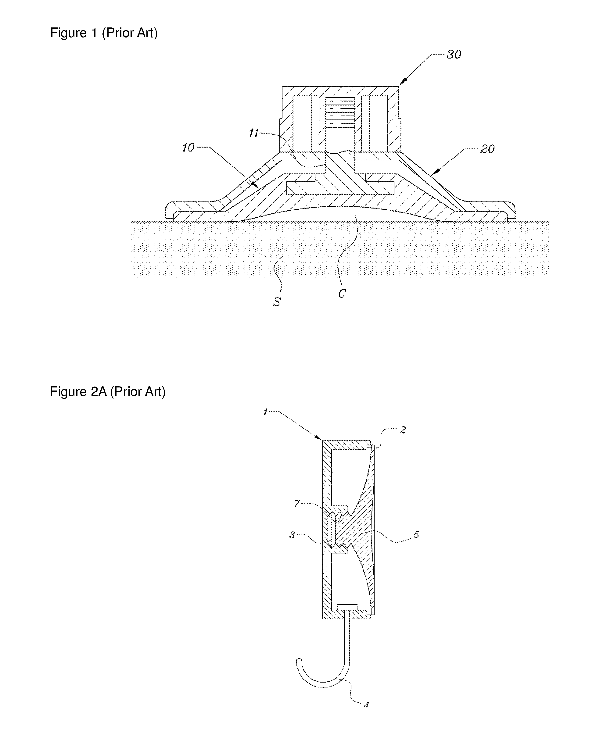
[0025]Hereunder, the present invention is described in detail by using the attached figures. However, in FIGS. 3 through 6 for description of the present invention, an independent name and figure number are assigned to each component regardless of FIGS. 1 and 2 for introduction of the conventional technology. And the attached FIGS. 3 through 6 introduce the Examples for easier description of the present invention. Thus, the scope of protection for the present invention is not limited by the Examples.

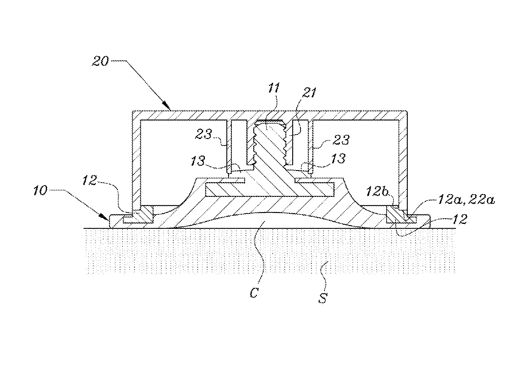
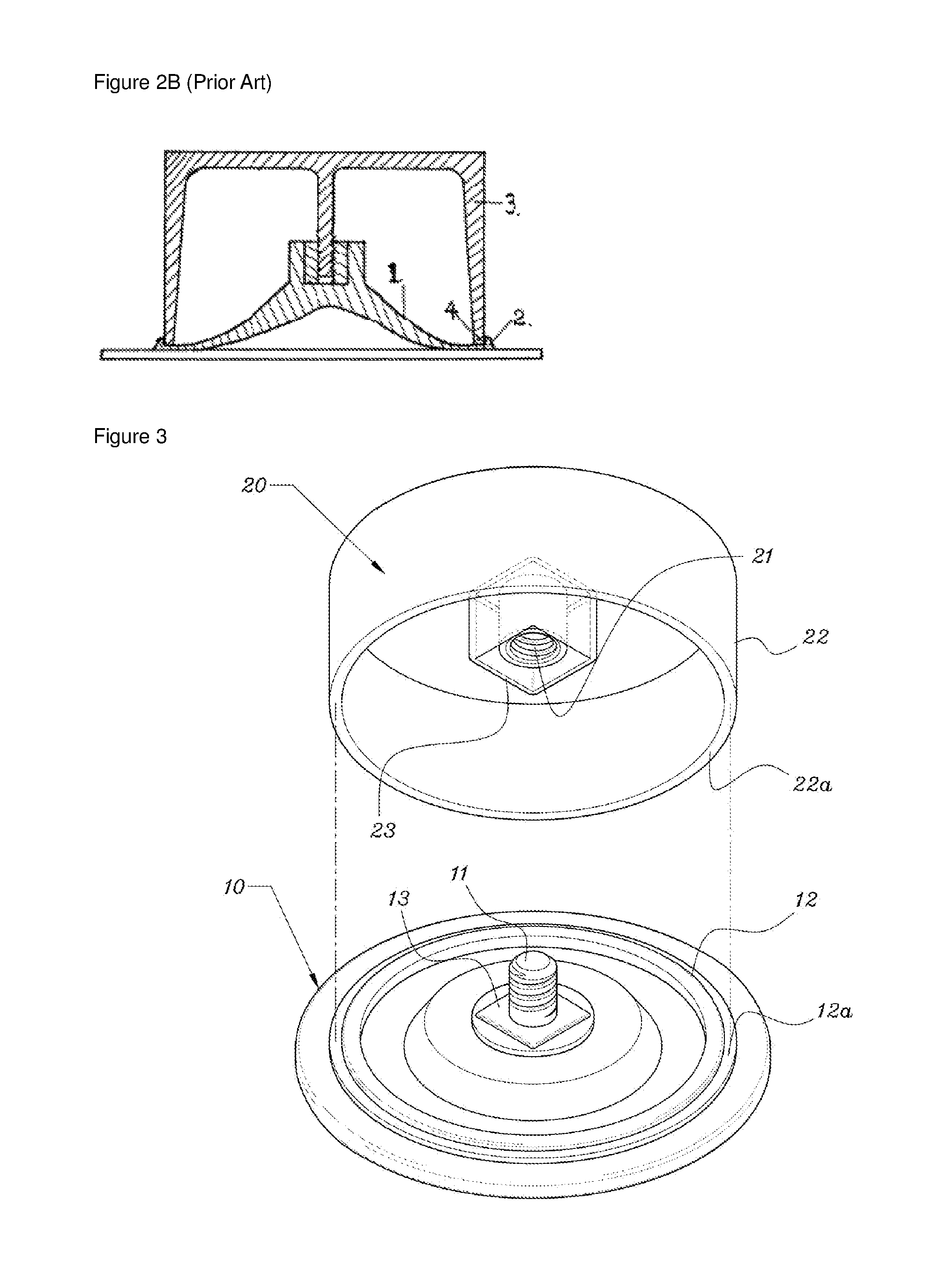
[0026]As shown in FIGS. 3 and 4, the rail-type vacuum fixer based on the present invention consists of the suction plate (10) and the rotary cap (20).

[0027]First of all, the said suction plate (10) is made of a flexible soft material, and the bottom surface sealed to the attached surface has a flat structure. At the center of the top surface for the said suction plate (10), the screw bar (11) is installed in the vertical direction. In the outer area of the top surface, the rotary rail (1...


PUM


Abstract

The present invention relates to a rail-type vacuum fixer, and more specifically relates to the rail-type vacuum fixer with a two-piece structure composed of a suction plate, on which a screw bar is installed at the center of the top surface and a hard rotary rail is installed in the circumferential direction in the areas of the top surface, and a rotary cap, which has a screw pipe inserted by the said screw bar at the center of the inside and is equipped in the border area with a sliding rim corresponding to the said rotary rail.

Description

BACKGROUND OF THE INVENTION[0001](a) Field of the Invention[0002]The present invention relates to a rail-type vacuum fixer, and more specifically relates to the rail-type vacuum fixer with a two-piece structure composed of a suction plate, on which a screw bar is installed at the center of the top surface and a hard rotary rail is installed in the circumferential direction in the areas of the top surface, and a rotary cap, which has a screw pipe inserted by the said screw bar at the center of the inside and is equipped in the border area with a sliding rim corresponding to the said rotary rail.[0003](b) Description of the Related Art[0004]The rail-type vacuum fixer is a household item to simply attach towel hangers or soap cases to mirrors or tile walls by using a soft suction plate like an octopus sucker. It is very convenient since it is easy to change the attachment position depending on the need and no attachment trace is left. The vacuum fixers with a variety of structures have...

Claims


Application Information

Patent Timeline
IPC IPC(8): A45D42/14F16B47/00F16M13/02
CPCF16B47/00F16M13/022F16B47/003
Inventor LEE, KYE-YOON
Owner GOODSENSE
Why Eureka
Try Eureka