Cavitation-based hydro-fracturing simulator

a hydro-fracturing simulator and cavitation technology, applied in the field of geothermal system enhancement, can solve the problems of reducing heat exchange efficiency, avoiding the movement of faults, and avoiding effective control

Active Publication Date: 2016-11-22
UT BATTELLE LLC
View PDF12 Cites 8 Cited by
  • Summary
  • Abstract
  • Description
  • Claims
  • Application Information

AI Technical Summary

Problems solved by technology

A potential drawback of using hydrofracking techniques is the lack of effective control in the creation of large fractures, which could result in by-pass of targeted fracture network or even fault movement in the rock formation.
The loss of hydraulic medium can reduce heat exchange efficiency and increase the cost of the development of EGS.
The use of chemicals along with the unpredictable fault movement may also adversely impact the environment.
Ultimately, the dynamic stress can contribute to the fatigue of the target surface, including micro-cracks that form and coalesce on the surface 204, eventually leading to material removal known as cavitation damage.
The operations of geothermal, oil and natural gas wells are expensive endeavors.

Method used


Image

  • Cavitation-based hydro-fracturing simulator
  • Cavitation-based hydro-fracturing simulator
  • Cavitation-based hydro-fracturing simulator

Examples


Embodiment Construction

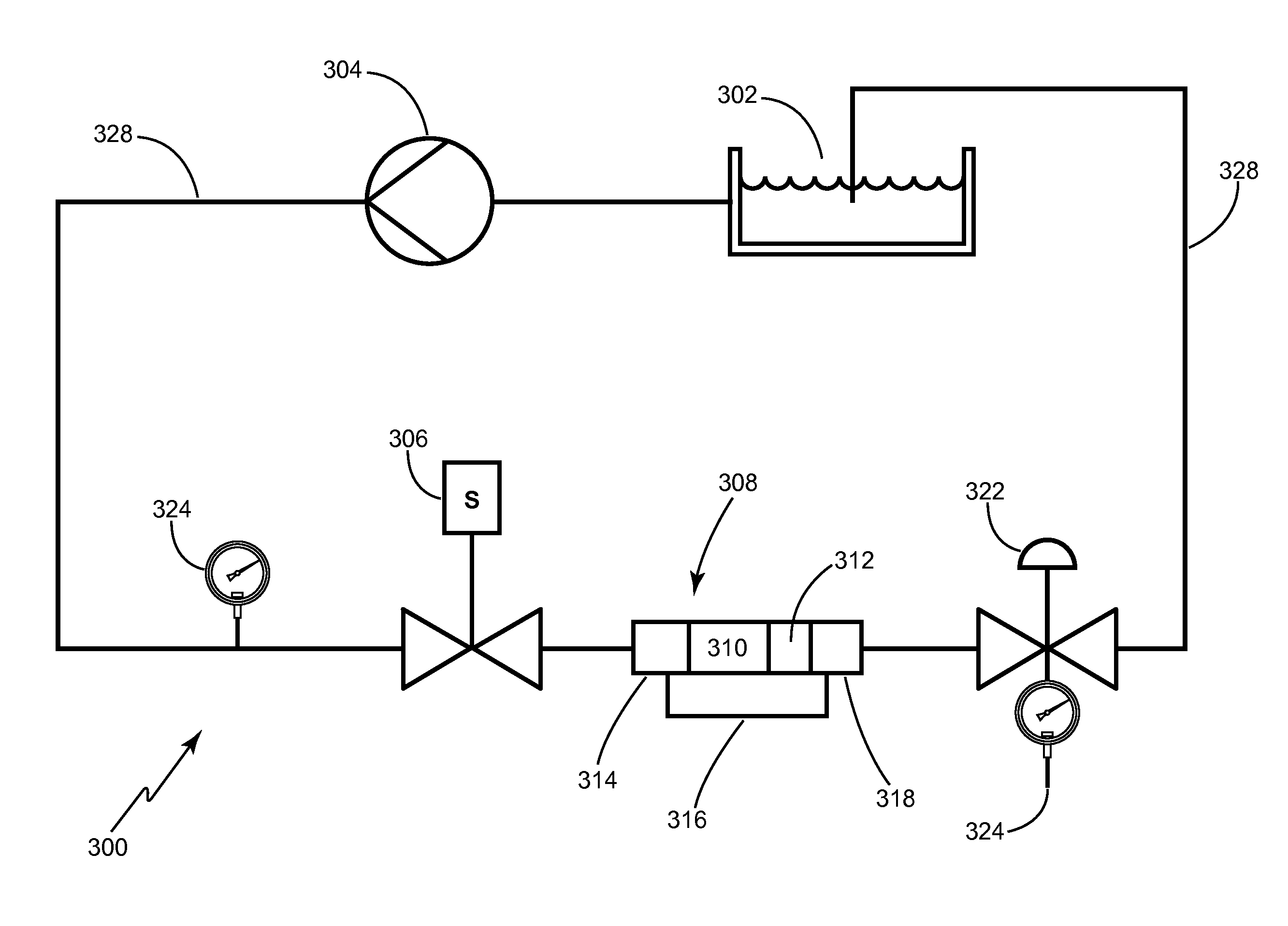
[0033]With reference now to FIG. 3, an exemplary apparatus 300 for generating a pulsed pressure induced cavitation technique to simulate the hydrofracturing of a specimen will now be described in greater detail. A working fluid (F), such as water, hydraulic fluid, other fluid, or combination of fluids, is stored in a reservoir 302. The reservoir 302 may be an open or closed vessel and may also include means for filtering, adding, removing, and / or monitoring the level of working fluid (F). A pump 304 draws the working fluid (F) from the upstream reservoir 302 and distributes it to one or more downstream control valves 306 at pressures less than or equal to approximately 300 psi (2068.4 kPa), greater than or equal to approximately 300 psi (2068.4 kPa), or greater than or equal to approximately 300 psi (2068.4 kPa) and less than or equal to approximately 2,000 psi (13789.5 kPa). The pump 304 may operate by compressed air or by an electric motor for example. An air operated liquid pisto...


PUM

PropertyMeasurementUnit
pressureaaaaaaaaaa
pressureaaaaaaaaaa
pressureaaaaaaaaaa

Abstract

An apparatus 300 for simulating a pulsed pressure induced cavitation technique (PPCT) from a pressurized working fluid (F) provides laboratory research and development for enhanced geothermal systems (EGS), oil, and gas wells. A pump 304 is configured to deliver a pressurized working fluid (F) to a control valve 306, which produces a pulsed pressure wave in a test chamber 308. The pulsed pressure wave parameters are defined by the pump 304 pressure and control valve 306 cycle rate. When a working fluid (F) and a rock specimen 312 are included in the apparatus, the pulsed pressure wave causes cavitation to occur at the surface of the specimen 312, thus initiating an extensive network of fracturing surfaces and micro fissures, which are examined by researchers.

Description

STATEMENT REGARDING FEDERALLY SPONSORED RESEARCH AND DEVELOPMENT[0001]This invention was made with government support under Contract No. DE-AC05-00O822725 awarded by the U.S. Department of Energy. The government has certain rights in the invention.CROSS-REFERENCE TO RELATED APPLICATIONS[0002]This patent application is related to U.S application Ser. No. 14 / 224,367 filed on 25 Mar. 2014 and entitled, “A CAVITATION-BASED HYDRO-FRACTURING TECHNIQUE FOR GEOTHERMAL RESERVOIR STIMULATION”, and U.S patent application Ser. No. 12 / 945,252 filed on 12 Nov. 2010 and entitled, “REPETITIVE PRESSURE-PULSE APPARATUS AND METHOD FOR CAVITATION DAMAGE RESEARCH” the entire contents of which are included herein by reference as if included at length.THE NAMES OF THE PARTIES TO A JOINT RESEARCH AGREEMENT[0003]None.BACKGROUND OF THE INVENTION[0004]1. Field of the Invention[0005]The present disclosure relates to enhanced geothermal system (EGS) production and particularly to apparatuses and methods for sim...

Claims


Application Information

Patent Timeline
Patent Type & Authority Patents(United States)
IPC IPC(8): E21B43/26G01N29/24G01N3/56F17D1/08H05B7/18E21B49/00B23K26/12
CPCE21B43/26B23K26/122E21B49/006F17D1/08G01N3/567G01N29/2418H05B7/18G01N2203/0055Y10T137/0391
Inventor WANG, JY-AN JOHNWANG, HONGREN, FEICOX, THOMAS S.
Owner UT BATTELLE LLC
Why Eureka
Try Eureka