Electrical submersible pump flow meter

a technology of flow meter and submerged pump, which is applied in the direction of fluid removal, survey, and wellbore/well accessories, etc., can solve the problems of not being able to provide accurate flow rates, replacing surface single-phase meters with multi-phase meters can cost tens of thousands of dollars per well, etc., to improve the operational performance of the esp, increase the capability of esp monitoring tools, and ensure the accuracy of flow meter

Active Publication Date: 2016-11-22
SAUDI ARABIAN OIL CO
View PDF23 Cites 9 Cited by
  • Summary
  • Abstract
  • Description
  • Claims
  • Application Information

AI Technical Summary

Benefits of technology

[0008]By adding a pressure sensing means to existing ESP monitoring tools a reliable cost affective single phase flow meter is obtained. This invention expands the capability of ESP monitoring tools by adding single phase oil-water flow meter capability through the addition of sensors below the ESP. Just as the ESP monitoring tool sensor data is now transmitted by the existing ESP cable, the flow meter will be able to do the same with communication on power. This will provide the capability of monitoring real time flow rates to improve the operational performance of the ESPs. The cost of adding a means for measuring flow rate downhole would be substantially absorbed by the already existing need for an ESP pressure or temperature sensor and the ESP power cable which will also be used to transmit the flow meter data, in real time to surface.
[0009]The flow meter of the current application is simple in design, has no moving parts and can utilize existing ESP monitoring tool and power cable for data transmission. Application of embodiments of the current application allows for a cost effective means of providing valuable information for improving the life of the ESP.

Problems solved by technology

If wells are producing below bubble point pressure, the liberated gas, at the surface, may not allow the surface meters to provide accurate flow rates.
To replace the surface single phase meters with multi-phase meters can cost tens of thousands of dollars per well.

Method used


Image

  • Electrical submersible pump flow meter
  • Electrical submersible pump flow meter
  • Electrical submersible pump flow meter

Examples


Embodiment Construction

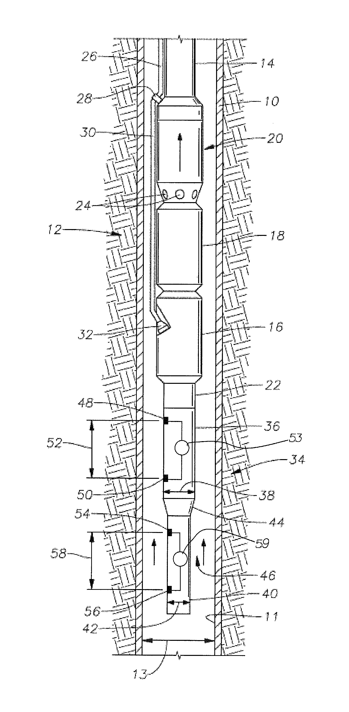
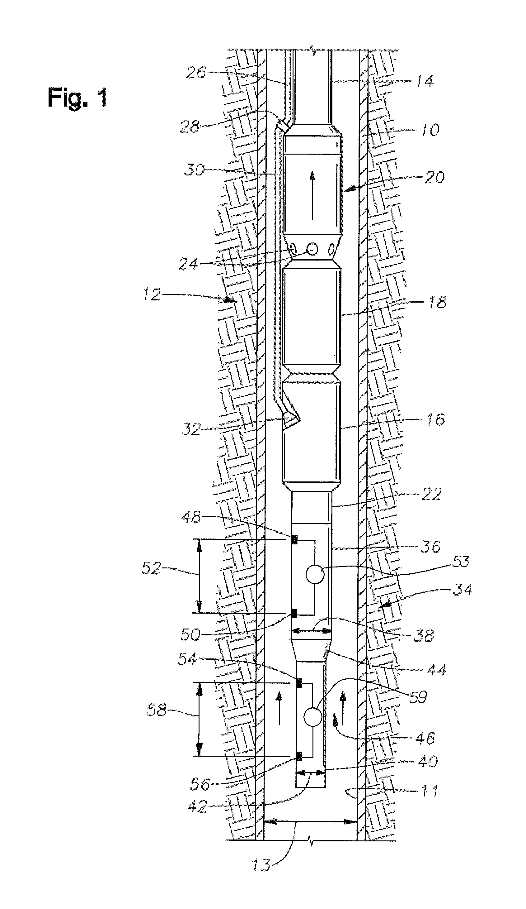
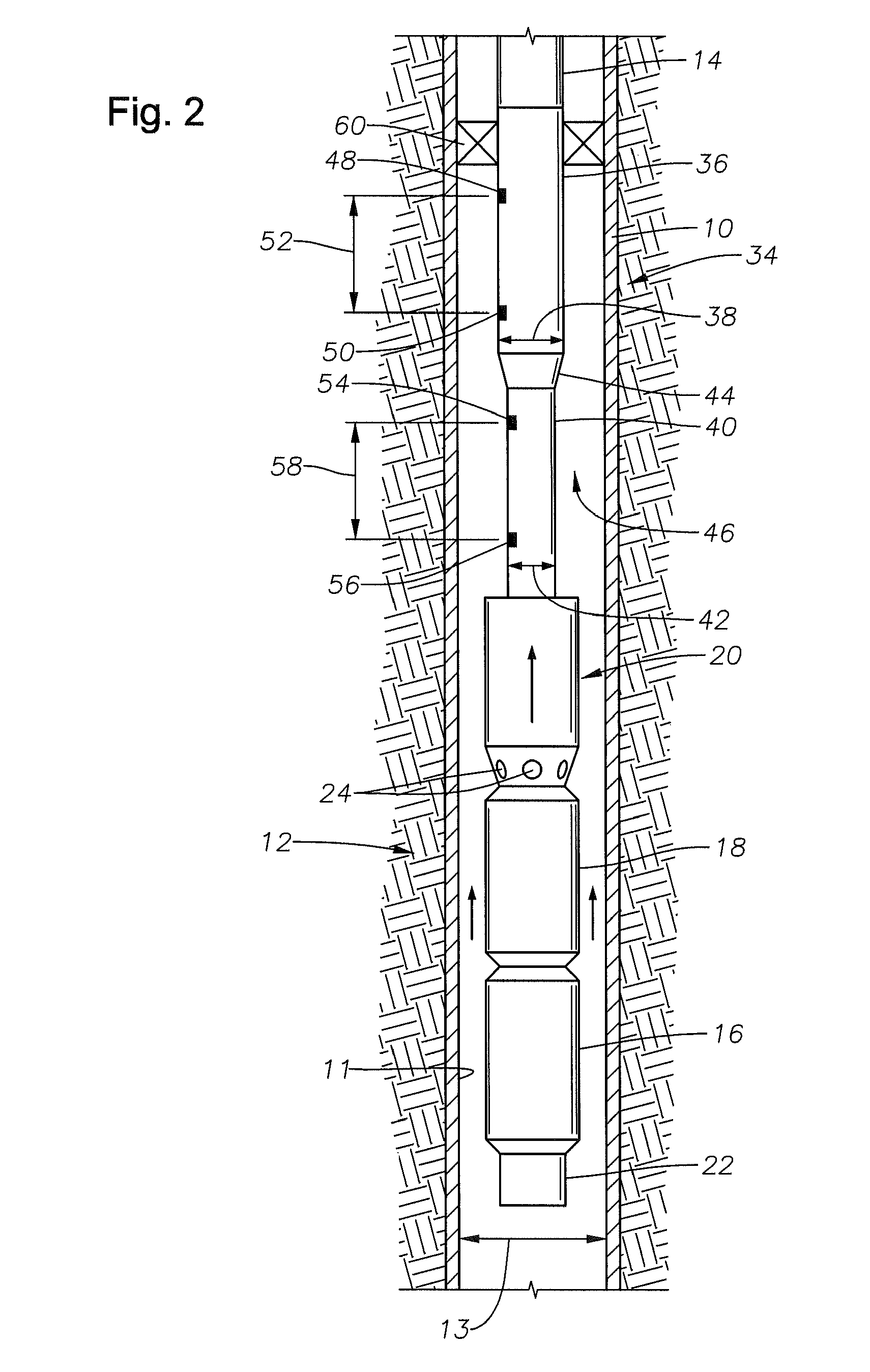
[0018]FIG. 1 is an elevational view of a well 10 having an electric submersible pump (“ESP”) 12 disposed therein, mounted to a string of tubing 14. Well 10 has in internal bore 11 with a diameter 13. ESP 12 includes an electric motor 16, and a seal section 18 disposed above motor 16. Seal section 18 seals well fluid from entry into motor 16. ESP also includes a pump section comprising pump assembly 20 located above seal section 18. The pump assembly may include, for example, a rotary pump such as a centrifugal pump. Pump assembly 20 could alternatively be a progressing cavity pump, which has a helical rotor that rotates within an elastomeric stator. An ESP monitoring tool 22 is located below electric motor 16. Monitoring tool 22 may measure, for example, various pressures, temperatures, and vibrations. ESP 12 is used to pump well fluids from within the well 10 to the surface. Fluid inlets 24 located on pump assembly 20 which create a passage for receiving fluid into ESP 12.

[0019]In ...


PUM


Abstract

An apparatus for metering fluid in a subterranean well includes an electric submersible pump having a motor, a seal section and a pump assembly and a metering assembly. The metering assembly includes an upper pipe section with an outer diameter, the upper pipe section having an upper pressure sensing means, and a lower pipe section with an outer diameter smaller than the outer diameter of the upper pipe section, the lower pipe section having a lower pressure sensing means. A power cable is in electronic communication with the electric submersible pump and with the metering assembly.

Description

CROSS-REFERENCE TO RELATED APPLICATION[0001]This application claims priority to provisional application 61 / 540,639 filed Sep. 29, 2011.BACKGROUND OF THE INVENTION[0002]1. Field of the Invention[0003]The present invention relates to electrical submersible pumps. More specifically, the invention relates a flow meter used in conjunction with an electrical submersible pump.[0004]2. Description of the Related Art[0005]In hydrocarbon developments, it is common practice to use electric submersible pumping systems (ESPs) as a primary form of artificial lift. ESPs often use downhole monitoring tools to supply both temperature and pressure readings from different locations on the ESP. For example, intake pressure, discharge pressure, and motor temperature, as well as other readings may be taken on the ESP.[0006]If wells are producing below bubble point pressure, the liberated gas, at the surface, may not allow the surface meters to provide accurate flow rates. To replace the surface single ph...

Claims


Application Information

Patent Timeline
Patent Type & Authority Patents(United States)
IPC IPC(8): E21B47/10E21B47/06E21B43/12E21B47/00E21B21/08E21B44/00
CPCE21B47/10E21B43/128E21B47/06
Inventor XIAO, JINJIANGSHEPLER, RANDALL ALAN
Owner SAUDI ARABIAN OIL CO
Why Eureka
Try Eureka