Load testing apparatus

a technology of load testing and load tubes, which is applied in the direction of power supply testing, instruments, measurement instrument housings, etc., can solve the problems of difficult transportation of load testing apparatuses through narrow spaces such as elevators, and achieve the effect of easy transportation and setup

Active Publication Date: 2016-11-22
TATSUMI
View PDF7 Cites 1 Cited by
  • Summary
  • Abstract
  • Description
  • Claims
  • Application Information

AI Technical Summary

Benefits of technology

[0006]One or more embodiment of the present invention are directed to a load testing apparatus that is configured with a plurality of resistance units and can be transported and set up easily.
[0009]After carrying in the base part, the resistance unit, and the cooling fan, work steps such as positioning considering the positional relationship among the base parts and connecting cables between resistance units need to be conducted. These work steps are easier than securing the resistance unit and the cooling fan to the base part or wiring inside the resistance unit, and therefore can easily be conducted at the site where the load testing apparatus is set up.
[0010]Even when the base parts are positioned in a manner making contact with each other, the resistance units do not touch each other, maintaining a gap of the second distance or larger, because the frame of each resistance unit is positioned in the inner side than the outer profile of the base part. Thus the separately provided base parts can easily be disposed, maintaining insulation between the resistance units.
[0011]In particular, the second distance can be set to 90 mm or larger in the present invention, and thus the insulation between adjacent two resistance units can be maintained even when a voltage of 6600 V is impressed on each of the two resistance units.
[0020]Use of the coupling switch unit including the first bus bar and the switching unit allows efficient wiring of components constituting the load testing apparatus.
[0028]According to one or more embodiments of the present invention, a load testing apparatus that is configured with a plurality of resistance units and can be transported and set up easily, can be provided.

Problems solved by technology

So that the large sized load testing apparatus needs to be transported with the resistance units and the base part assembled, which makes it difficult to transport the load testing apparatus through a narrow space, such as an elevator.

Method used


Image

  • Load testing apparatus
  • Load testing apparatus
  • Load testing apparatus

Examples


Embodiment Construction

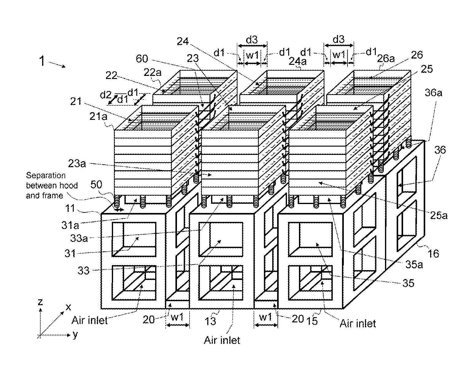
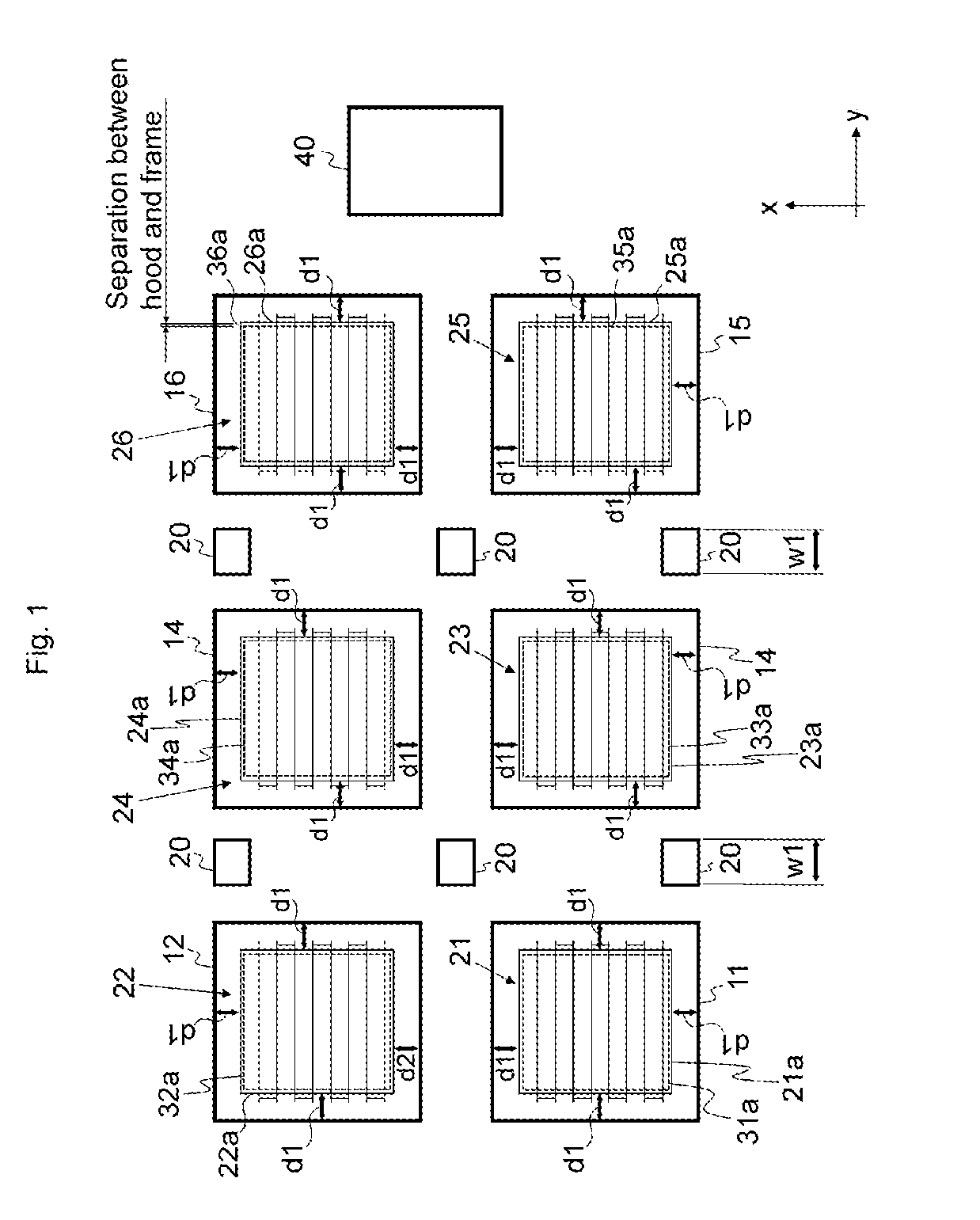
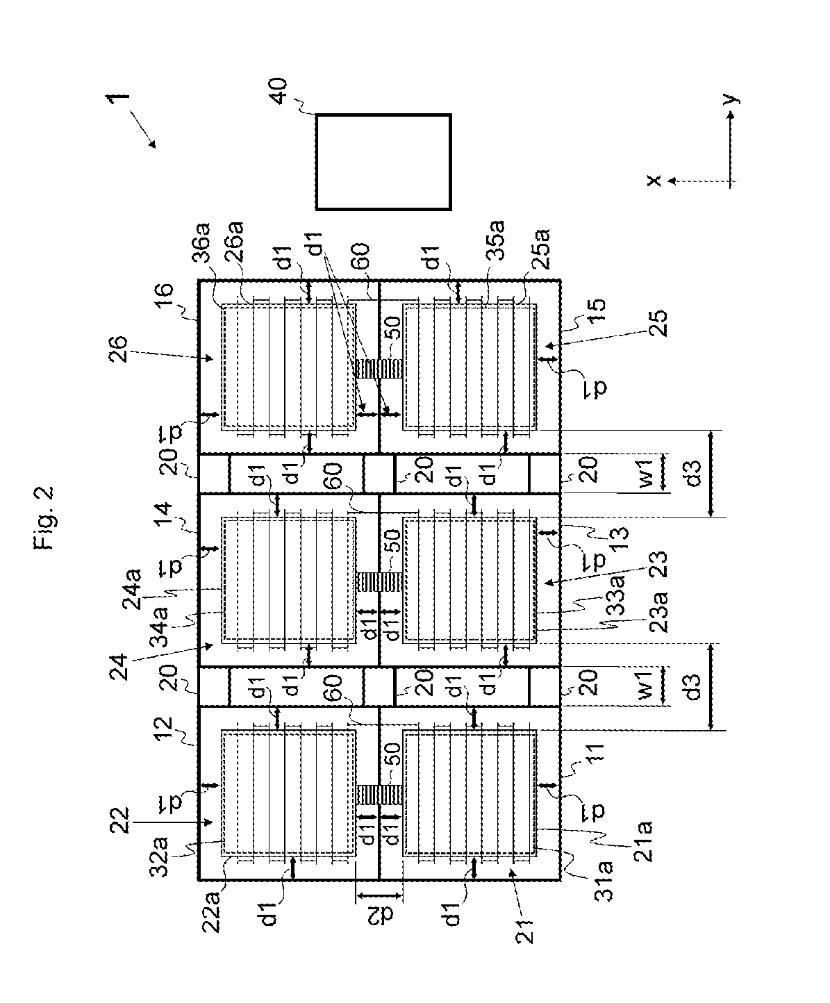
[0056]An embodiment will be described below referring to the drawings. A dry load testing apparatus 1 according to the embodiment includes a first base part 11 to a sixth base part 16, gap adjusting members 20, a first resistance unit 21 to a sixth resistance unit 26, a first cooling fan 31 to a sixth cooling fan 36, a power source connector 40, insulators 50, and a coupling cable 60 (see FIGS. 1 to 13).

[0057]The configuration of each component will be described first, and then the wiring between the power source connector 40 and each resistance unit will be described (see FIGS. 14 to 24). In FIGS. 1 to 13, components related to wirings, such as a coupling switch unit 70, are omitted.

[0058]The first base part 11 has an approximately cuboid external form. The first cooling fan 31 is provided in the upper portion of the first base part 11. An air inlet for the first cooling fan 31 is provided on a side face or the bottom face in the lower portion of the first base part 11. An exhaust ...


PUM


Abstract

A load testing apparatus includes at least two resistance units each configured with a plurality of resistor-groups arranged in stages along z direction, which is a vertical direction, and including a frame configured with an insulating material covering a side face of the resistor-groups, each of the resistor-groups including resistors arrayed along a horizontal direction; and at least two base parts each including a cooling fan and provided separately. At least one of the resistance units are provided on a top of each of the base parts via an insulator. A face of the frame that at least faces another adjacent resistance unit is positioned in an inner side of a side face of the base part, on which the resistance unit is provided, by a first distance when viewed from above. The at least two resistance units are disposed to have a gap between the frames of adjacent resistance units, the gap being equal to or larger than a second distance to provide insulation between the adjacent resistance units. The second distance is twice the first distance. The first distance is equal to or larger than 45 mm.

Description

CROSS-REFERENCE TO RELATED APPLICATIONS[0001]This application is a continuation application of International Patent Application No. PCT / JP2014 / 004062 filed on Aug. 4, 2014, which claims priority to International Patent Application No. PCT / JP2014 / 000944 filed on Feb. 24, 2014, the entire contents of which are incorporated by reference.TECHNICAL FIELD[0002]The present invention relates to load testing apparatuses used for an electric load test of a power source such as an alternate-current generator.BACKGROUND ART[0003]A dry load testing apparatus using a resistance unit including an array of resistors is proposed.CITATION LISTPatent Literature[0004]Patent Literature 1: JP 2010-25752 ASUMMARY OF INVENTION[0005]If the voltage for a load test of a power source is high, a large sized load testing apparatus in which a plurality of resistance units is disposed is needed. The large sized load testing apparatus has a base part integrated with a plurality of resistance units mounted on the ba...

Claims


Application Information

Patent Timeline
Patent Type & Authority Patents(United States)
IPC IPC(8): G01R31/40G01R1/04H01C13/02
CPCG01R31/40G01R1/04H01C13/02G01R31/42H02J2203/20Y02E60/00Y04S40/20G01R1/203G01R1/206G01R31/34
Inventor KONDO, TOYOSHI
Owner TATSUMI
Why Eureka
Try Eureka