Supercharge Your Innovation With Domain-Expert AI Agents!

Image sensor with shading detection

a technology of image sensor and shading detection, which is applied in the field of image sensor, can solve the problems of lens vignetting cannot be avoided, the output signal of the pixels is “shaded” and the problem becomes even more complicated

Active Publication Date: 2016-11-22
HARVEST IMAGING
View PDF10 Cites 0 Cited by
  • Summary
  • Abstract
  • Description
  • Claims
  • Application Information

AI Technical Summary

Benefits of technology

The present invention aims to provide an image sensor and a digital camera that can efficiently use the light sensitive area. In this embodiment, shading correction is performed in the digital domain, which re-uses the same hardware component. This improves the quality and performance of the image sensor and digital camera.

Problems solved by technology

One of the problems with such cameras or image sensors is the problem of “shading” of the output signal provided by the pixels.
1) Natural vignetting of the lens: all lenses have an intensity fall-off towards the corners of the sensor (away from the optical axis). This decrease in intensity of the incoming signal can be empirically described (cos4-law), and is depending on the focal length f and the F number of the lens. An example of the natural lens vignetting is shown in FIG. 1A. In the embodiment illustrated, the intensity decrease goes from 100% at the centre of the lens to 52% at the corners, but of course another value is also possible. An example of a fall-off curve is illustrated underneath the represented lens in FIG. 1A, but this is not limiting the present invention in any way. Other fall-off curves do occur. The lens vignetting cannot be avoided, even not in the most expensive lenses for professional applications.
2) Sensor vignetting: light rays fall nicely perpendicular on the sensor when they are parallel to the optical axis. But that is not the case in the corners of the sensor. Here the incoming rays come to the sensor with a deviating angle (known as the “chief ray angle”) to the normal. It is well known that the sensitivity of the sensor is the highest for perpendicularly incoming light. Thus pixels that receive the incoming information under an angle deviating from the normal to the sensor provide a reduced output signal. It should be noted that this effect is depending on the focal length f of the lens, the F number of the lens, but also on the wavelength of the incoming radiation (due to the dispersive characteristics of the materials). A simple example of sensor vignetting is shown in FIG. 1B. In this figure the sensor vignetting shown is illustrated without taking into account the dependency on the wavelength.
3) Filter vignetting: most colour cameras use several optical filters in front of the image sensor (e.g. IR-filter, optical low-pass filter, etc). The transmission characteristics of these filters depend also on the angle of the incoming rays, as well as on the wavelength of the incoming light. In other words, the external filters add to the shading as well. An example of the vignetting caused by an IR-filter is shown in FIG. 1C. As can be seen from the figure, the transmission in the corners (e.g. 90%) is reduced compared to the centre transmission (e.g. 100%). But moreover, the attenuation is different for the various colours (e.g. 90% for red, 97% for green, 99% for blue). The red spectrum suffers most from this type of vignetting.
4) It can be seen from the above that there are several contributions to the shading. Ideally all shading components are nicely circular-symmetric w.r.t. the optical axis, but unfortunately that is not always the case. The problem becomes even more complicated when the shading of the three colours components has a different shape, or when their optical axes do not coincide. FIG. 1D shows an example of non-circular-symmetric colour shading (although not very well visible on a black and white picture). The top left of the image has too much red output, while the bottom right has too much blue output. This figure shows that the shading components (R, G, B) may change for every pixel location of the image sensor.
This extra space (substrate area such as e.g. silicon area) does not yield extra image data, thus does not yield a higher resolution picture, and is therefore not efficiently used.
A disadvantage of this image sensor 100 of FIG. 2 is that its light sensitive area is not efficiently used.

Method used


Image

  • Image sensor with shading detection
  • Image sensor with shading detection
  • Image sensor with shading detection

Examples


first embodiment

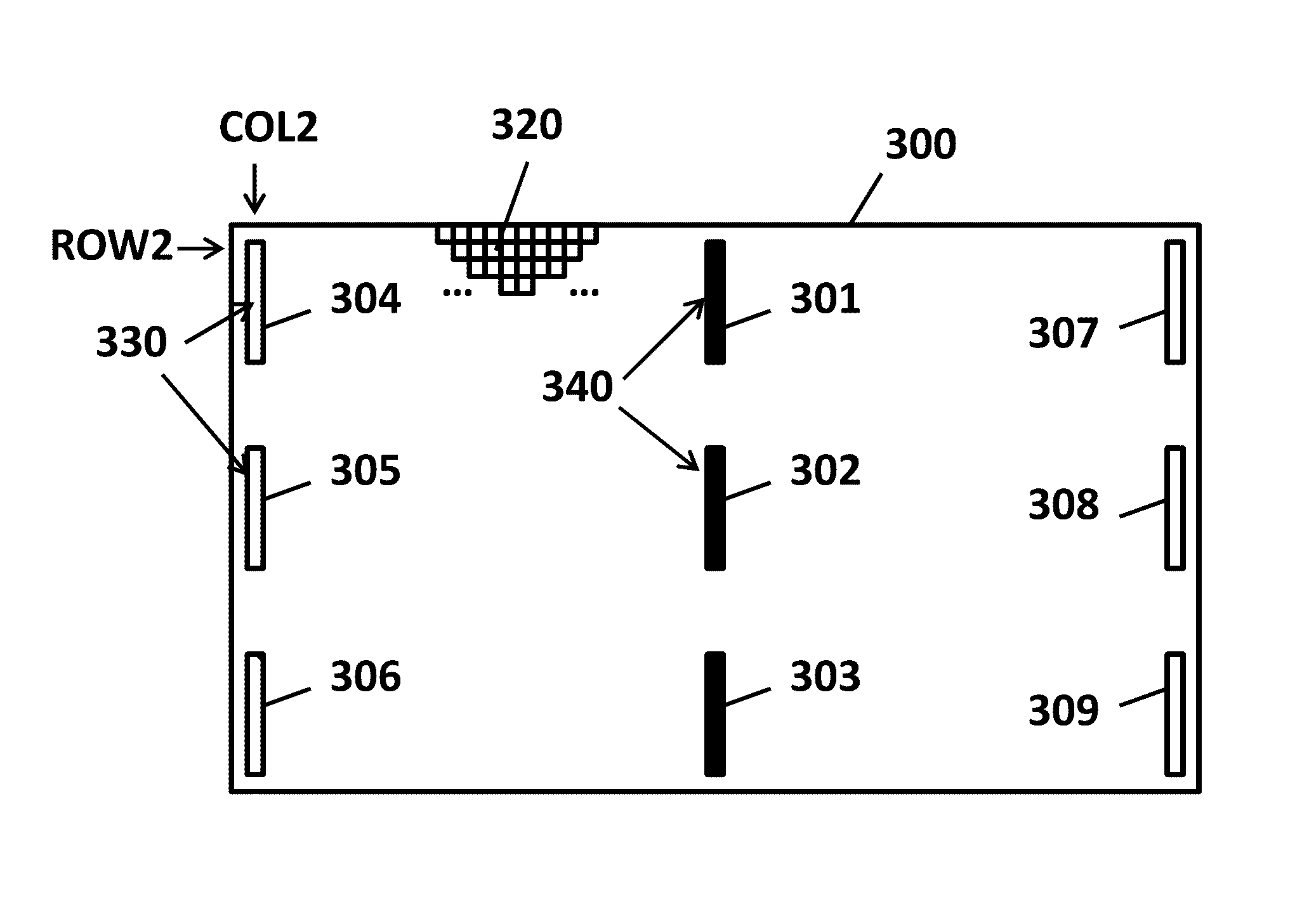
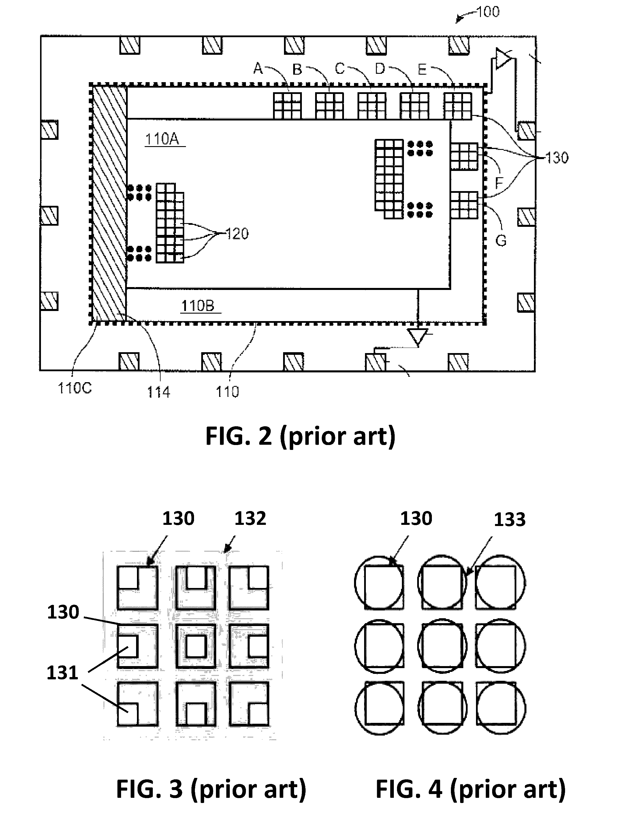
[0098]FIG. 5 shows a first embodiment of an image sensor 300 according to aspects of the present invention. The image sensor 300 comprises a plurality of image pixels 320 and a plurality of shading detection pixels 330. Each image pixel 320 and shading pixel 330 and (optional) focus detection pixel 340 (if present) has a photoelectric conversion element such as e.g. a photodiode for converting impinging radiation, e.g. light energy, into electrical energy, but only the image pixels are adapted, e.g. optimized for capturing image data. An aspect of the present invention is that the shading detection pixels of all embodiments of the present invention are located in the same area, e.g. rectangular area, as defined by the (normal) image pixels 320. The shading pixels 330 effectively take the place of some of the image pixels 320, in contrast to the prior art image sensor 100 (of FIG. 2), where the shading pixels 130 are located outside of the area occupied by the (normal) image pixels 1...

second embodiment

[0113]FIG. 8 shows a second embodiment of an image sensor 400 according to aspects of the present invention. The image sensor 400 comprises a plurality of image pixels 420 and a plurality of shading detection pixels 430, the latter being organized in blocks of 1×9 pixels (i.e. arrays of 1 row and 9 consecutive columns). The shading pixels 430 are located in the same rectangular area as the area defined by the image pixels 420, and they effectively replace some of the image pixels.

[0114]The main difference between this embodiment and that of FIG. 5 is that the blocks 404 to 409 of shading pixels are arranged horizontally as 1×9 arrays, instead of vertically as 9×1 arrays. The image sensor 400 may optionally comprise focus detection pixels 440, which in the embodiment illustrated are arranged also horizontally, although that is not absolutely required. All the advantages described for the first embodiment are also applicable here. Furthermore, there may be an additional advantage in t...

third embodiment

[0124]FIG. 12 shows a third embodiment of an image sensor 500 according to aspects of the present invention. The image sensor 500 comprises a plurality of image pixels 520 and a plurality of shading detection pixels 530. The shading detection pixels are organized in blocks of 5×5 pixels comprising sixteen image pixels 520 and nine shading pixels 530. Also in this embodiment, the shading pixels 530 are located in the same rectangular area as the image pixels 520, (i.e. the area defined by the image pixels), and the shading pixels take the place of some of the image pixels.

[0125]The main difference between this embodiment and that of FIG. 5 is that the blocks 504 to 507 of shading pixels are arranged as square blocks, instead of partial columns. Optionally, the image sensor 500 of FIG. 12 further comprises focus detection pixels 540, which are arranged in the example of FIG. 12 in horizontal and vertical zones 501, 502, 503, but any other arrangement of the focus detection pixels may ...


PUM


Abstract

An image sensor comprising a plurality of pixels arranged in rows and columns, the plurality of pixels comprising: image pixels arranged for providing image data, and shading detection pixels arranged for providing signals from which a degree of shading can be derived, wherein the shading detection pixels are located in substantially the same area as defined by the image pixels.

Description

FIELD OF THE INVENTION[0001]The present invention relates to the field of image sensors, and more particularly to image sensors having both image pixels and shading detection pixels.BACKGROUND OF THE INVENTION[0002]Digital cameras with a solid-state image sensor, in particular for example CMOS image sensors comprising a plurality of image pixels, located at a distance of a lens, are known in the art.[0003]One of the problems with such cameras or image sensors is the problem of “shading” of the output signal provided by the pixels. Shading is the effect of a non-constant low spatial frequency output signal of the image sensor, even under uniform lighting conditions. This can be due to several reasons, for example:[0004]1) Natural vignetting of the lens: all lenses have an intensity fall-off towards the corners of the sensor (away from the optical axis). This decrease in intensity of the incoming signal can be empirically described (cos4-law), and is depending on the focal length f an...

Claims


Application Information

Patent Timeline
Patent Type & Authority Patents(United States)
IPC IPC(8): G06T15/50H04N9/04H04N3/14H04N5/357H04N5/369
CPCH04N9/045H04N5/3572H04N5/3696H04N23/67H04N25/61H04N25/704H04N25/611H04N23/843H04N25/134
Inventor THEUWISSEN, ALBERT
Owner HARVEST IMAGING
Features
  • R&D
  • Intellectual Property
  • Life Sciences
  • Materials
  • Tech Scout
  • Unparalleled Data Quality
  • Higher Quality Content
  • 60% Fewer Hallucinations
Learn More