Radiographic imaging apparatus and method

a radiographic and imaging apparatus technology, applied in the field of radiographic imaging apparatus, can solve the problems of significant signal degradation, erroneous binning of detected radiation into incorrect energy bins, and baseline shift of signals output by detector pixels, and achieve a simple and robust way of persistent current compensation

Active Publication Date: 2016-11-29
KONINKLJIJKE PHILIPS NV
View PDF15 Cites 16 Cited by
  • Summary
  • Abstract
  • Description
  • Claims
  • Application Information

AI Technical Summary

Benefits of technology

[0006]It is an object of the present invention to provide a radiographic imaging apparatus and method that provide a simple and robust way of persistent current compensation.
[0023]According to the present invention the X-ray blanking by use of a slit anode (also called slotted anode) is combined with the PC sensing intervals of a photon counting detector. Further, the persistent output current of the photon counting unit of the photon counting detector is sensed in a blanking interval during which no X-ray radiation is emitted. The sensed persistent output current is then used to correct a detector signal generated by said photon counting unit in a subsequent measurement interval during which X-ray radiation is emitted by said X-ray source. This provides for the desired simple and efficient way of persistent current compensation.
[0029]In still another embodiment said switch is controlled by a blanking signal to be synchronously with the measurement intervals of the photon counting X-ray detector and between two successive measurement intervals. This embodiment has the advantage to keep the measurement intervals constant. This avoids the need to compensate varying measurement intervals.

Problems solved by technology

Direct conversion material such as CdTe and CZT tends to produce a low frequency electrical current when irradiated with X-rays, which results in a baseline shift of the signals output by the detector pixels.
Unfortunately, the baseline shift shifts the pulse output by the shaper, which can lead to erroneous binning of the detected radiation into incorrect energy bins as the discriminator thresholds remain static.
This persistent current causes significant signal degradation and may generate unacceptable image artefacts if left uncorrected.
Unfortunately, the persistent current dynamically changes and cannot simply be compensated with a static signal of the opposite sign like the dark current.

Method used


Image

  • Radiographic imaging apparatus and method
  • Radiographic imaging apparatus and method
  • Radiographic imaging apparatus and method

Examples


first embodiment

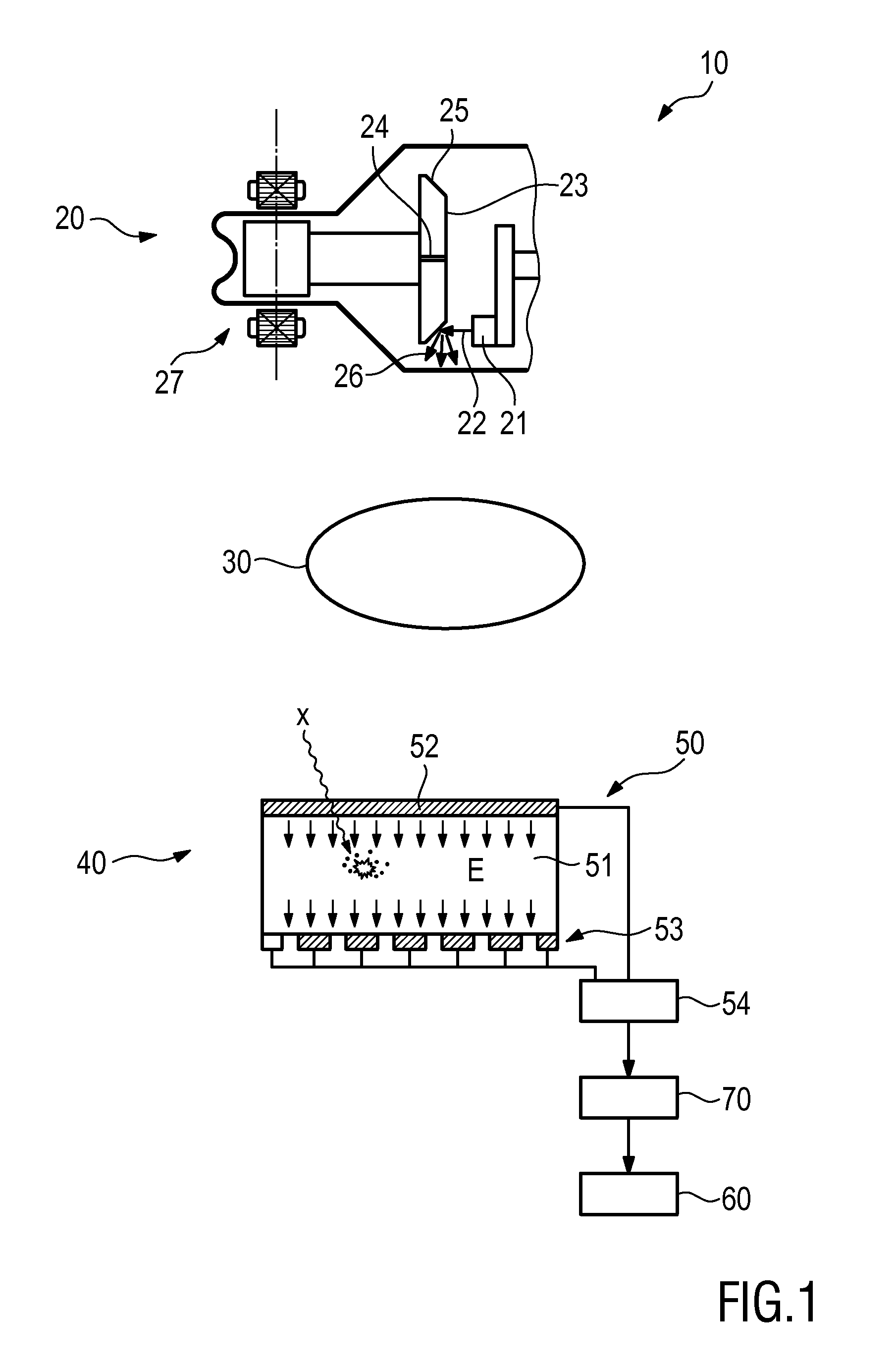
[0036]FIG. 1 shows a proposed radiographic imaging apparatus 10. It comprises an X-ray source 20 for projecting X-ray radiation into an examination region 30 and a photon counting X-ray detector 40 for receiving X-ray radiation after passing through said examination region 30 and converting the received X-ray radiation into detector signals. In the examination region an object of examination, e.g. a patient, may be placed, e.g. lying on a patient table as generally known in the art.

[0037]The X-ray source 20 comprises a cathode 21 for emitting an electron beam 22 and a rotary X-ray anode 23 having a number of radial slits 24 and a target layer 25 provided on a surface of said rotary X-ray anode 23 in between said radial slits 24 for emitting X-ray radiation 26 when hit by said electron beam 22. A drive unit 27, e.g. formed as an electric motor comprising a rotor and a stator body, is provided for rotating said X-ray anode 23.

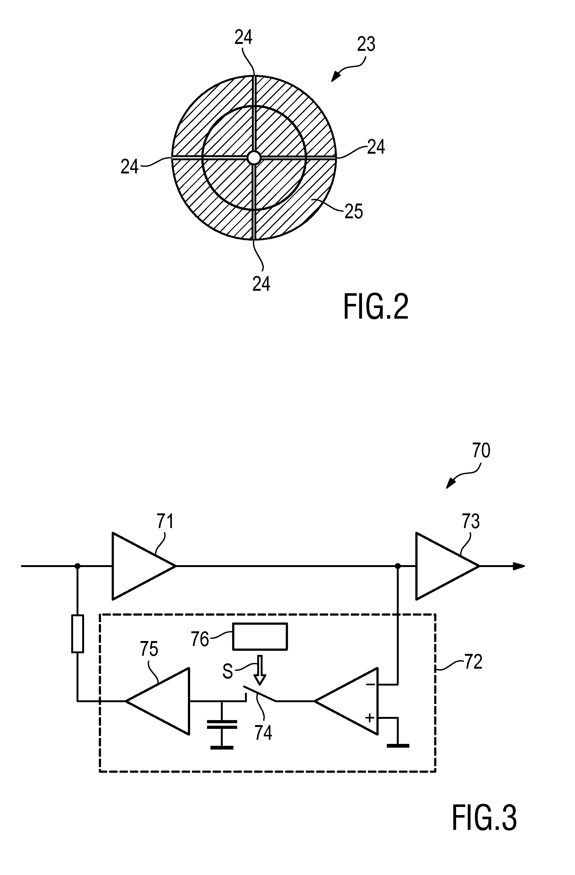
[0038]A top view on a rotary X-ray anode 23 having—in this ...

second embodiment

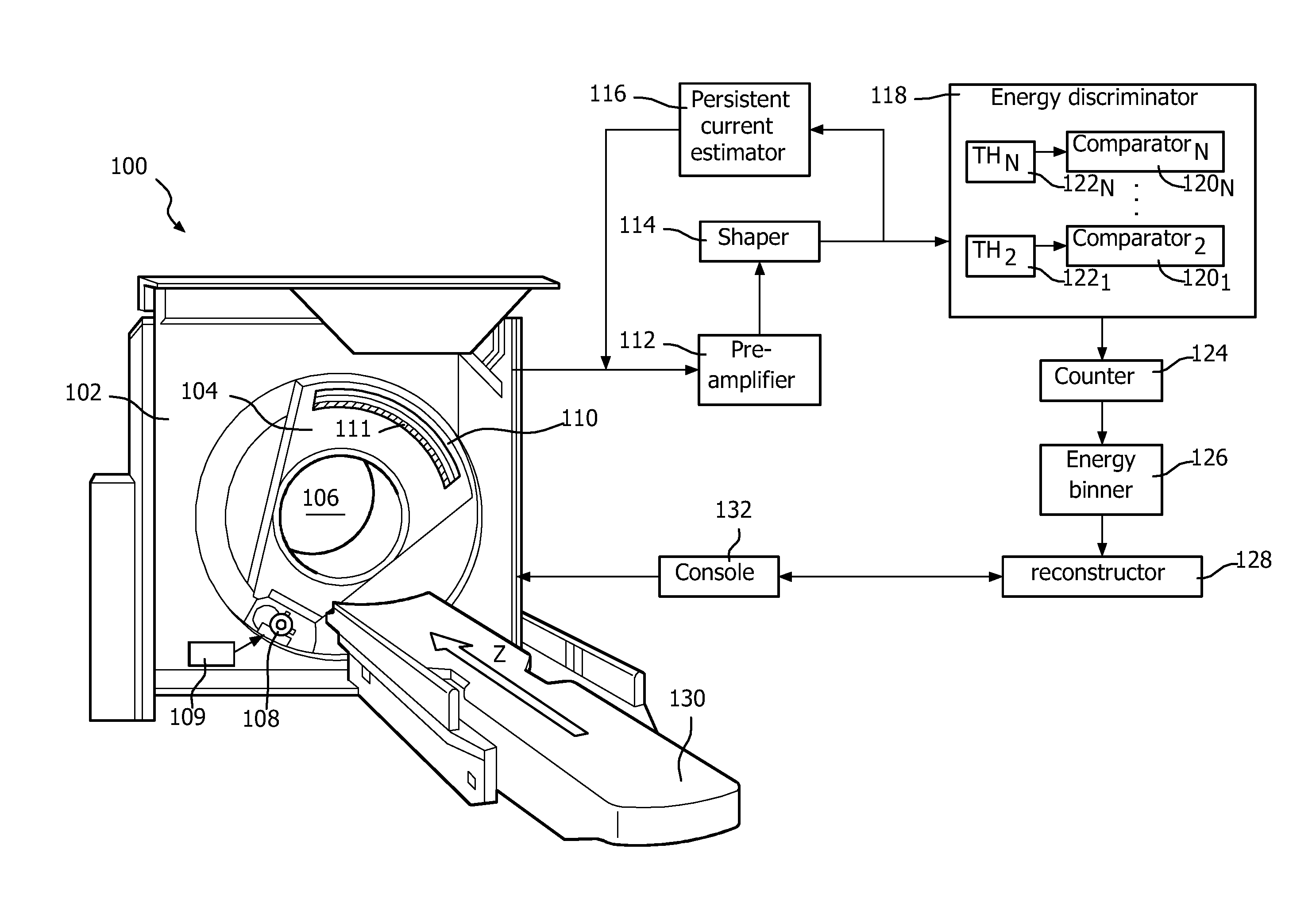
[0048]FIG. 4 shows a proposed radiographic imaging apparatus 100 which is implemented as a computed tomography (CT) scanner. The imaging apparatus 100 includes a stationary gantry 102 and a rotating gantry 104, which is rotatably supported by the stationary gantry 102. The rotating gantry 104 rotates around an examination region 106 about a z-axis. A radiation source 108, such as an X-ray tube, is supported by and rotates with the rotating gantry 104 around the examination region 106 about the z-axis. The source 108 emits radiation that traverses the examination region 106. An optional radiation controller 109 transitions a state of radiation emission between a first state in which radiation traverses the examination region 106 and a second state in which radiation does not traverse the examination region 106. This may include turning the source 108“on” / “off,” inserting / removing a filter from the path of radiation, applying / removing a grid voltage to a switching grid of the source 1...


PUM


Abstract

The present invention relates to a radiographic imaging apparatus and a corresponding radiographic imaging method. The proposed apparatus comprises an X-ray source (20, 108) and a photon counting X-ray detector (40, 110). The X-ray source (20, 108) comprises a rotary X-ray anode (23) having a number of radial slits and a target layer provided on a surface of said rotary X-ray anode in between said radial slits for emitting X-ray radiation when hit by said electron beam. The said photon counting X-ray detector (40, 110) comprises a persistent current sensing and correction unit (70) for sensing a persistent output current in a blanking interval during which no X-ray radiation is emitted by said X-ray source and for using the sensed persistent output current to correct a detector signal in a subsequent measurement interval during which X-ray radiation is emitted by said X-ray source.

Description

CROSS REFERENCE TO RELATED APPLICATIONS[0001]This application is a national filing of PCT application Serial No. PCT / IB2013 / 059092, filed Oct. 3, 2013, published as WO 2014 / 057400 A1 on Apr. 17, 2014, which claims the benefit of U.S. provisional application Ser. No. 61 / 712,877 filed Oct. 12, 2012, which is incorporated herein by reference.FIELD OF THE INVENTION[0002]The present invention relates to a radiographic imaging apparatus comprising an X-ray source for projecting X-ray radiation into an examination region and a photon counting X-ray detector for receiving X-ray radiation after passing through said examination region and converting the received X-ray radiation into detector signals. Further, the present invention relates to a corresponding radiographic imaging method.BACKGROUND OF THE INVENTION[0003]A computed tomography (CT) scanner generally includes a rotating gantry rotatably mounted to a stationary gantry. The rotating gantry supports an X-ray tube and is configured to ...

Claims


Application Information

Patent Timeline
Patent Type & Authority Patents(United States)
IPC IPC(8): H01J35/10H01J35/08G01T1/24A61B6/00G21K1/04
CPCA61B6/54A61B6/42G01T1/24H01J35/10G21K1/043H01J2235/086A61B6/4028A61B6/4035A61B6/4476
Inventor PROKSA, ROLAND
Owner KONINKLJIJKE PHILIPS NV
Why Eureka
Try Eureka