Noise suppression cable, core assembly, and electrical device

a technology of noise suppression cable and core assembly, which is applied in the direction of power cables, cables, inductances, etc., can solve the problems of complex device construction and operation, inability to control the emission direction of radiation noise, and inability to detect the signal-wire disconnection, etc., and achieves simple construction and suppression of radiation noise

Active Publication Date: 2016-11-29
HITACHI METALS LTD
View PDF9 Cites 1 Cited by
  • Summary
  • Abstract
  • Description
  • Claims
  • Application Information

AI Technical Summary

Benefits of technology

[0020]According to one embodiment of the invention, a noise suppression cable can be provided that is capable of suppressing the radiation noise and controlling the emission direction of the radiation noise, as well as a core assembly used for the noise suppression cable. Also, according to another embodiment of the invention, an electrical device can be provided that is capable of suppressing the radiation noise and detecting the signal-wire disconnection with a simple construction.

Problems solved by technology

The noise suppression cable disclosed in JP-A-H06-181012 can suppress the radiation noise, but cannot control the emission direction of the radiation noise.
Thus, a problem may arise that the detection of the signal-wire disconnection is complicated in device construction and operation.

Method used


Image

  • Noise suppression cable, core assembly, and electrical device
  • Noise suppression cable, core assembly, and electrical device
  • Noise suppression cable, core assembly, and electrical device

Examples


first embodiment

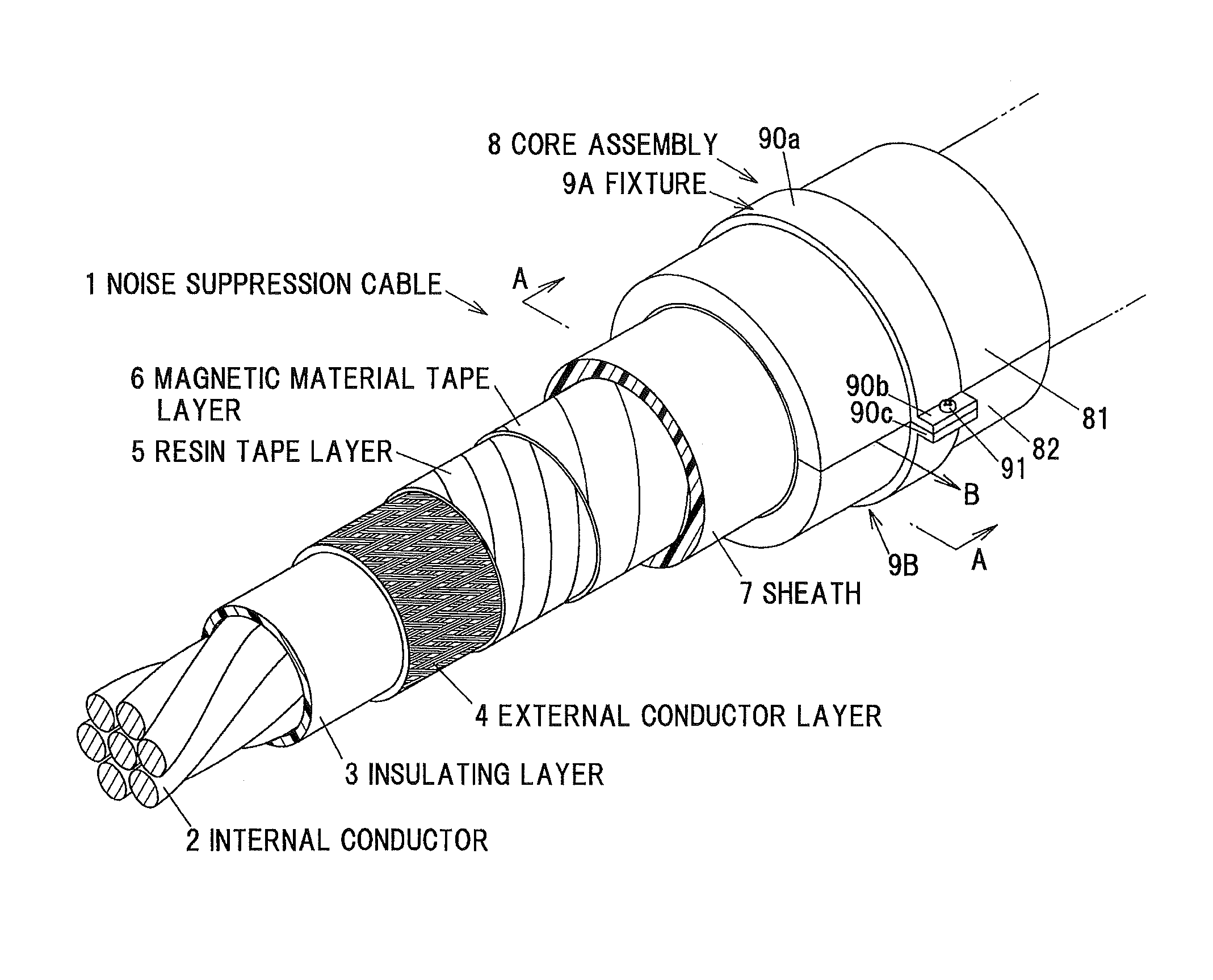
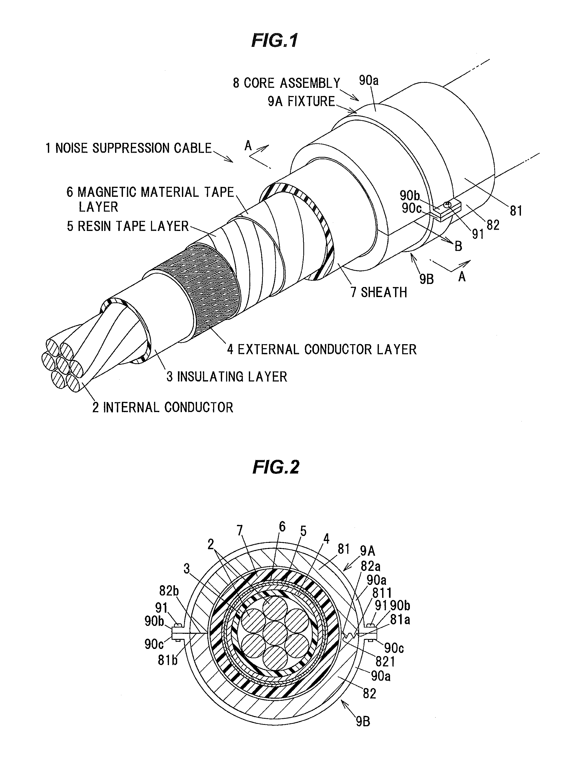
[0028]FIG. 1 is a perspective view schematically showing a noise suppression cable according to a first embodiment of the invention. FIG. 2 is a cross-sectional view taken along the line A-A in FIG. 1.

[0029]The noise suppression cable 1 includes internal conductors 2 constituted of a plurality (7 in the embodiment) of conductors which are stranded, an insulating layer 3 covering the periphery of a plurality of the internal conductors 2 so as to insulate the internal conductors, an external conductor layer 4 formed on the periphery of the insulating layer 3, a resin tape layer 5 formed on the periphery of the external conductor layer 4, a magnetic material tape layer 6 formed on the periphery of the resin tape layer 5, a sheath 7 formed on the periphery of the magnetic material tape layer 6 as an insulating protective layer, the sheath 7 being comprised of a resin or the like, a core assembly 8 formed on the periphery of the sheath 7, and a pair of fixtures 9A, 9B configured to fix t...

second embodiment

[0047]FIG. 4 is a top view schematically showing a control substrate according to the second embodiment of the invention. The control substrate 10 according to the embodiment is a substrate configured such that the noise suppression cable 1 according to the first embodiment is mounted. Hereinafter, different points from the first embodiment will be mainly explained.

[0048]The control substrate 10 according to the embodiment is mounted on, for example, an electrical device so as to control each part of the electrical device. The control substrate 10 includes a CPU 11 configured to execute a predetermined processing based on a program stored in a storage part not shown, a connection part 12 configured to connect the noise suppression cable 1 to the control substrate 10, a magnetic sensor 13 configured to detect the magnetic flux emitted from the core assembly 8 of the noise suppression cable 1 and a printed circuit board 100 configured such that the CPU 11, the connection part 12, the ...


PUM

PropertyMeasurementUnit
depthaaaaaaaaaa
depthaaaaaaaaaa
magneticaaaaaaaaaa

Abstract

A noise suppression cable includes an electrical wire, a first magnetic material including a pair of first surfaces formed along an axis direction of the electrical wire and a convex portion projecting from the first surfaces, and a second magnetic material including a pair of second surfaces disposed on a periphery of the electrical wire, the pair of the second surfaces contacting the pair of the first surfaces such that a tubular shape is formed by the first and second magnetic materials. The first magnetic material and the second magnetic material are configured to generate a compression stress in the convex portion of the first magnetic material by receiving an external force so as to reduce a relative permeability of the convex portion.

Description

[0001]The present application is based on Japanese patent application No. 2014-029737 filed on Feb. 19, 2014, the entire contents of which are incorporated herein by reference.BACKGROUND OF THE INVENTION[0002]1. Field of the Invention[0003]This invention relates to a noise suppression cable, a core assembly used for the noise suppression cable and an electrical device using the noise suppression cable.[0004]2. Description of the Related Art[0005]For suppressing a radiation noise from a cable, a noise suppression cable has been proposed which has a signal wire, a dielectric layer disposed outside the signal wire, and a shield layer disposed outside the dielectric layer and a magnetic material layer disposed outside the shield layer, the magnetic material layer of a material including a ferrite (e.g., refer to JP-A-H06-181012).[0006]For detecting the disconnection of an electrical wire, a disconnection detection device has been proposed which has a voltage detection part detecting a v...

Claims


Application Information

Patent Timeline
Patent Type & Authority Patents(United States)
IPC IPC(8): H01B11/04H01B9/00
CPCH01B9/006H05K9/0098H01F2017/065
Inventor NAKATANI, KATSUTOSHISUMI, YOSUKEAJIMA, KENJIAKIMOTO, KATSUYACHIWATA, NAOFUMIOKIKAWA, HIROSHIMUTO, YASUHARU
Owner HITACHI METALS LTD
Why Eureka
Try Eureka