Fluid pump changeable in diameter, in particular for medical application

a technology of fluid pump and diameter, applied in the field of precision mechanics, can solve the problems of tight limits placed on the expansion ability of such pumps, and achieve the effect of simple and large changeability of the diameter

Active Publication Date: 2016-12-06
ECP ENTWICKLUNGSGMBH
View PDF235 Cites 18 Cited by
  • Summary
  • Abstract
  • Description
  • Claims
  • Application Information

AI Technical Summary

Benefits of technology

[0009]In this context, it is the object of the present invention to create a fluid pump, which with as little as possible design effort, permits an as simple and as large as possible changeability of the diameter.
[0024]One achieves a particularly quiet and smooth running of the rotor by way of a further mounting at the distal end of the pump housing being provided additionally to a mounting at the proximal end of the pump housing. The respective bearing arrangement may likewise be movable relative to the pump housing within the framework of the invention. It is advantageously displaceable on the actuation means or its extension, in their longitudinal directions, or at least displaceable with the actuation means or the extension, with respect to the rotor and the pump housing, as long as the actuation means itself is displaceable in the longitudinal direction.
[0034]The struts in the braced condition may advantageously form an inflow cage at the distal end of the fluid pump, which on the one hand prevents the rotor from coming into contact with body tissue and one the other hand ensures that any larger coagulated masses, which are located in the fluid to be delivered, may not penetrate into the pump housing.
[0035]Moreover, it is advantageous to design the actuation means in a displaceable manner with respect to the sleeve in the longitudinal direction, in particular to the rotation drive at the proximal end of the sleeve, in order to effect the different axial displacement movements of the pump housing, the rotor and the bearing arrangement to one another.
[0038]Advantageously, the catheter is filled with a body-compatible fluid, for example a saline solution, in order on the one hand to prevent the penetration of gas bubbles into the body and on the other hand, as the case may be to lubricate and cool the shaft which usually rotates at 20′000-35′000 revolutions per minute.

Problems solved by technology

Since a certain size is necessary for an optimised performance of such a pump, which however is limited by the diameter of the large blood vessels of the body which end in the heart, it is already known to use fluid pumps which are changeable in their radius for this purpose, which may be expanded after introduction into the heart chamber.
However, tight limits are placed on the expansion ability of such pumps due to the necessity of accommodating a drive shaft as well as a rotor and pump housing within a small diameter.

Method used


Image

  • Fluid pump changeable in diameter, in particular for medical application
  • Fluid pump changeable in diameter, in particular for medical application
  • Fluid pump changeable in diameter, in particular for medical application

Examples


Embodiment Construction

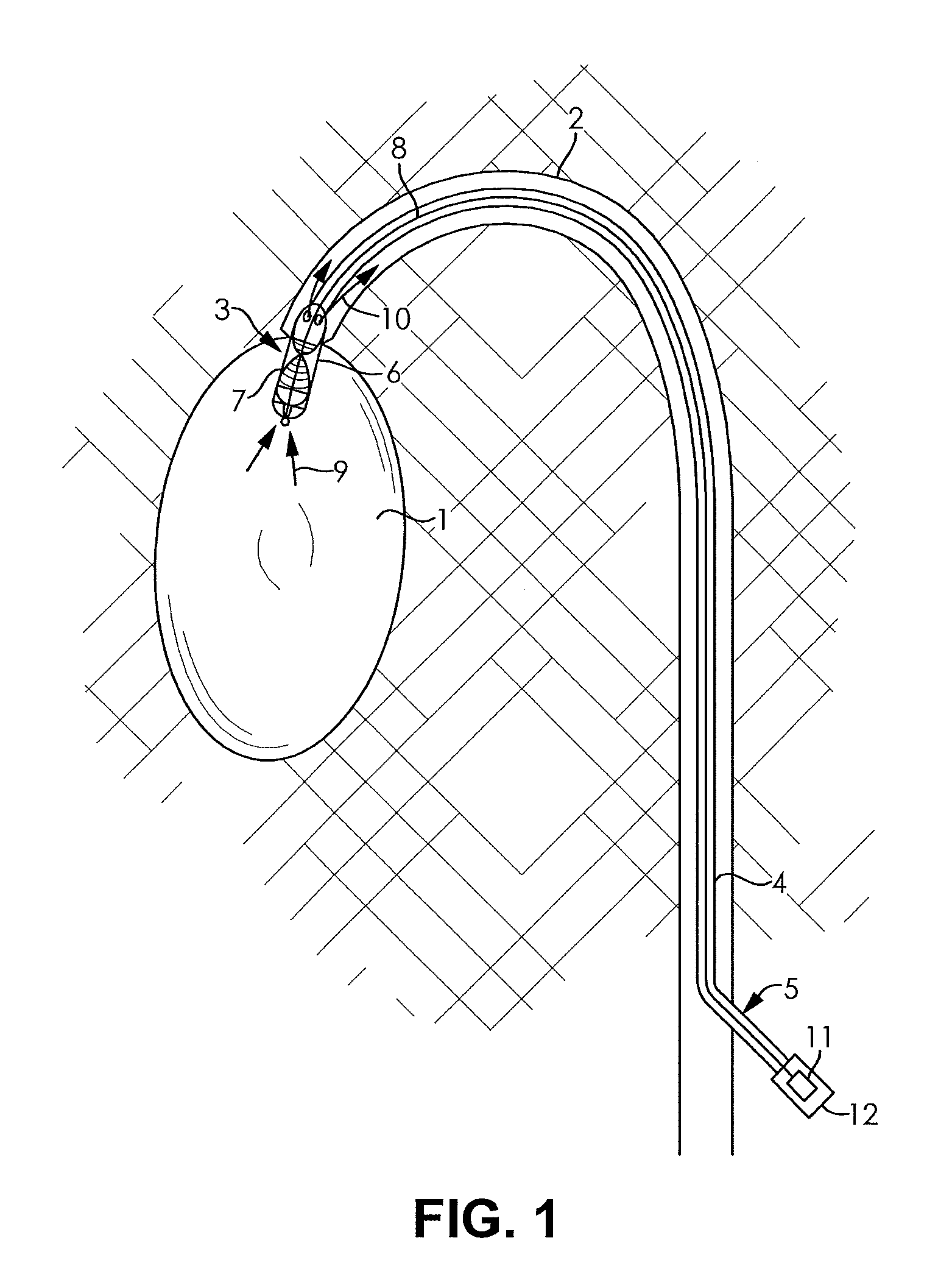
[0065]FIG. 1 shows a heart chamber, which is connected to a blood vessel 2, into which blood is to be pumped. For supporting the pump activity, a fluid pump 3 is introduced into the heart chamber 1, which there sucks blood and pumps this into the blood vessel 2.

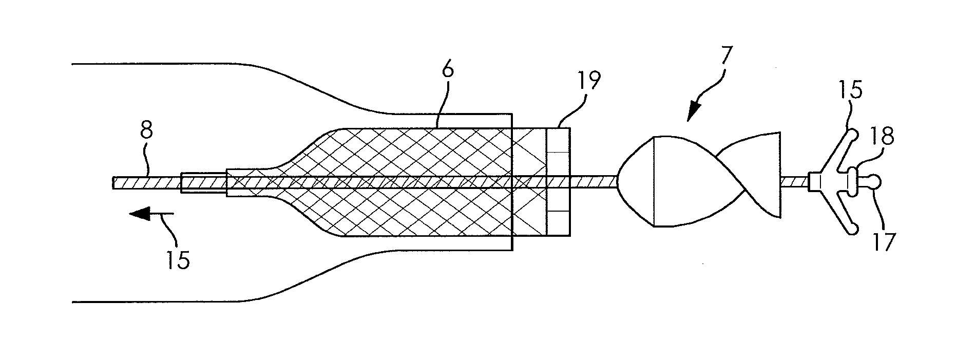
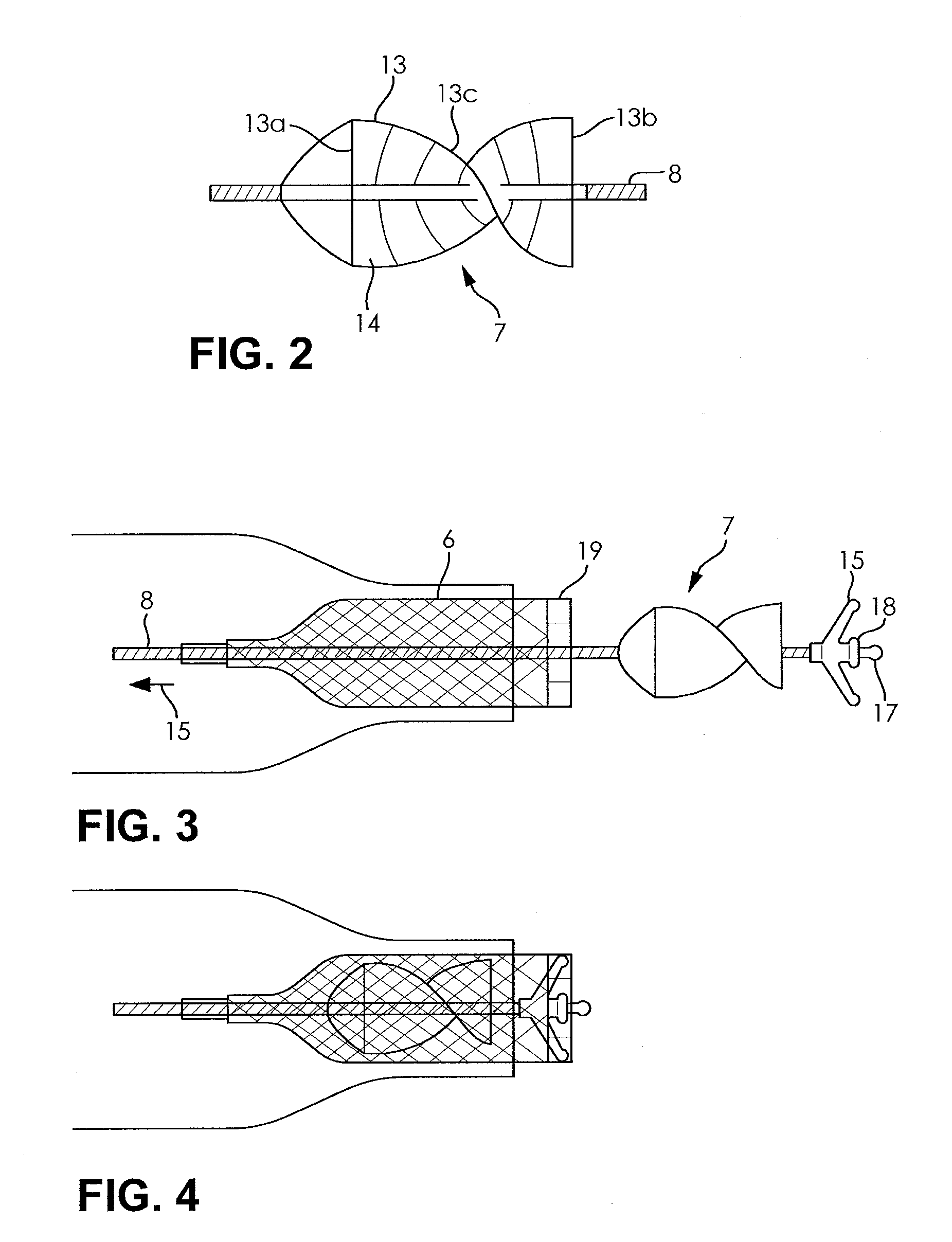
[0066]A catheter 4 is introduced through a lock 5 into the blood vessel 2, through which lock the catheter may also be pulled out again. The catheter 4 at its distal end carries the pump 3 in the form of a pump housing 6 connected to the catheter, and a rotor 7. The rotor 7 is rotatably mounted on a drive shaft 8 and comprises delivery elements, which on rotation suck the blood in the direction of the arrows 9 or eject it in the direction of the arrows 10 into the blood vessel 2. For this, the delivery elements in the shown representation, which shows the explained position of the fluid pump, have a helically arranged delivery blade surface.

[0067]The construction of the pump housing and the rotor will be dealt with in more de...


PUM


Abstract

A fluid pump device changeable in diameter is provided. The device has a pump housing which is changeable in diameter and with a rotor which is changeable in diameter. The device has at least one delivery element for fluid, as well as a drive shaft on which the rotor is rotatably mounted. A bearing arrangement is arranged on the drive shaft or its extension, at the distal end of the drive shaft behind the rotor seen from the proximal end of the drive shaft. The bearing arrangement has struts, which elastically brace between a hub of the bearing arrangement and the pump housing.

Description

RELATED APPLICATION[0001]This application is a continuation application of pending U.S. patent application Ser. No. 13 / 318,678 filed on Nov. 29, 2011, which is hereby incorporated by reference in its entirety.BACKGROUND OF THE INVENTION[0002]The invention lies in the field of mechanics, in particular precision mechanics, and may be advantageously applied to the medical field.[0003]However, independently of the application in the medial sector, applications in other fields may be envisaged, where a fluid pump is to be operated under restricted spatial conditions or at poorly accessible locations.[0004]This is particularly the case with minimal-invasive medical technology, where often medical instruments or apparatus must be brought to the location of application, for example through blood vessels, with an as gentle as possible treatment of the patient. It is particularly in this context that the application of blood pumps in combination with catheters has become known, which for exam...

Claims


Application Information

Patent Timeline
Patent Type & Authority Patents(United States)
IPC IPC(8): F04C2/02F04C14/22A61M1/10F04D29/18F04D29/24A61M60/13A61M60/165A61M60/237A61M60/414A61M60/808A61M60/81A61M60/825
CPCF04C14/22A61M1/101A61M1/1013A61M1/1024A61M1/1034F04C2/02F04D29/181F04D29/242Y10S415/90A61M60/405A61M60/414A61M60/419A61M60/422A61M60/148A61M60/808A61M60/81A61M60/237A61M60/13A61M60/165A61M60/825A61M60/135A61M60/818A61M60/205F04D29/043F04D29/046F04D29/528
Inventor LIEBING, REINER
Owner ECP ENTWICKLUNGSGMBH
Why Eureka
Try Eureka