Drying plant for particulate materials

a technology of drying plant and particulate material, which is applied in the field of drying plant for particulate material, can solve the problems of compromising the correct operation of the drying plant, reducing the free section of the drying duct, etc., and achieves the effect of eliminating the drawbacks

Active Publication Date: 2016-12-13
GARBUIO
View PDF27 Cites 5 Cited by
  • Summary
  • Abstract
  • Description
  • Claims
  • Application Information

AI Technical Summary

Benefits of technology

[0014]Aim of the present invention is to eliminate the drawbacks due to the presence of the bend along the drying duct of the cut tobacco drying plant.

Problems solved by technology

Unfortunately, while allowing a significant increase in the working length of the drying duct, the presence of the 90° bend on the duct causes anomalous distribution of the particles of cut tobacco in the flow of process gas which ascends the vertical section of the drying duct, at least partly thwarting the advantages due to the increased working length of the drying duct.
In addition, at the bend, the particles of cut tobacco tend to knock violently against the wall of the duct depositing on the surface tar-based oily residues which, over time, stratify on the surface of the wall, forming scale which further worsens the distribution of the particles of cut tobacco along the vertical section of the drying duct, and furthermore progressively reduces the free section of the drying duct, compromising correct operation of the drying plant in the long term.

Method used


Image

  • Drying plant for particulate materials
  • Drying plant for particulate materials
  • Drying plant for particulate materials

Examples


Embodiment Construction

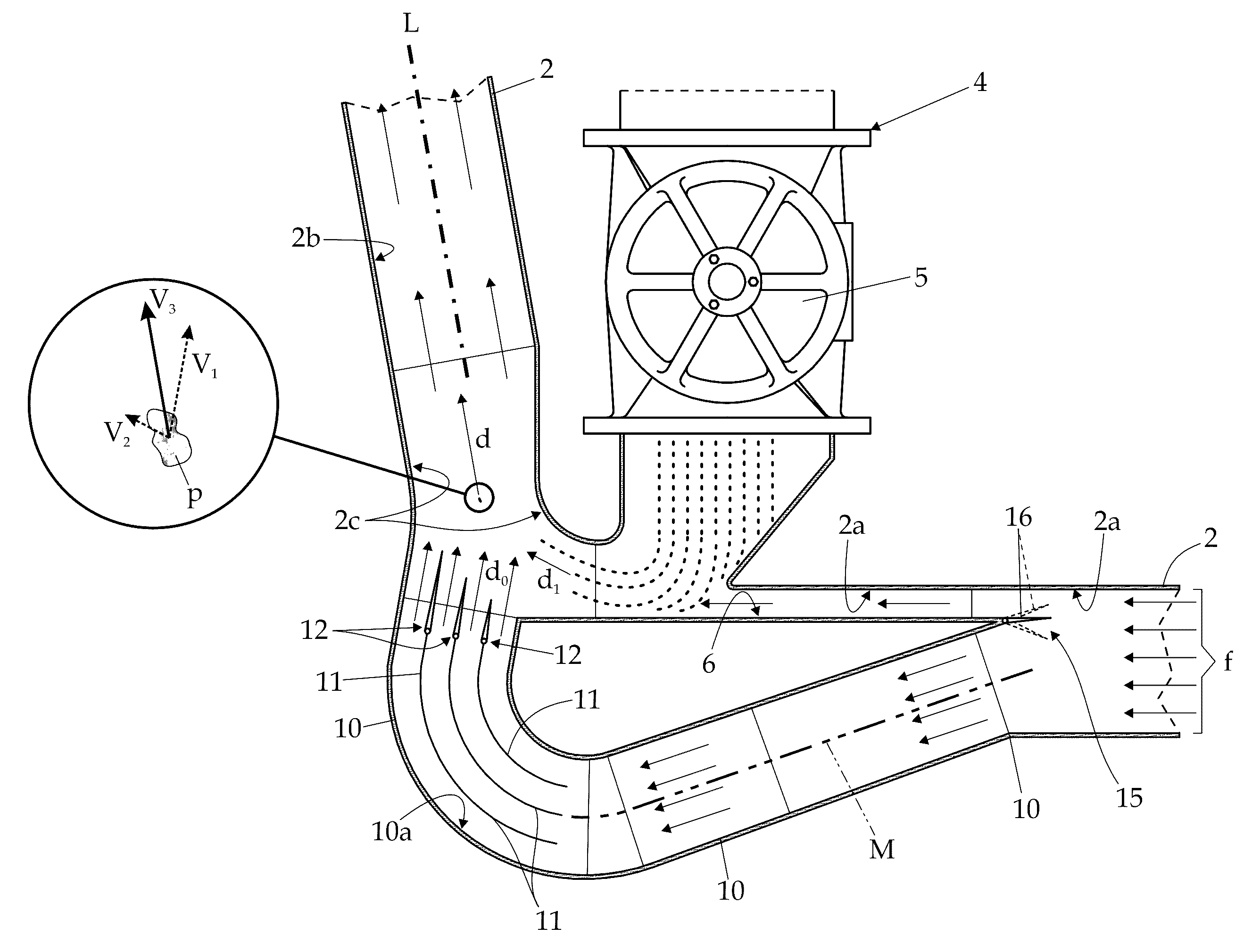
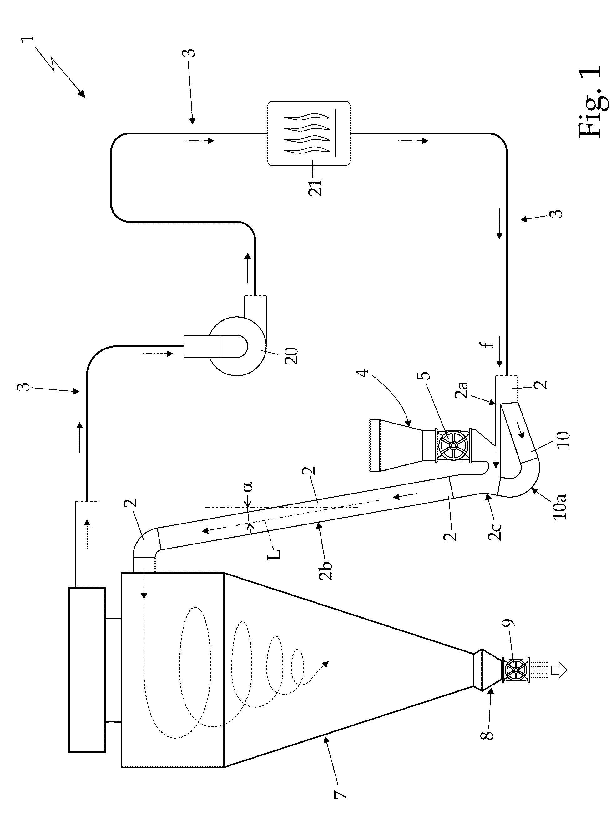
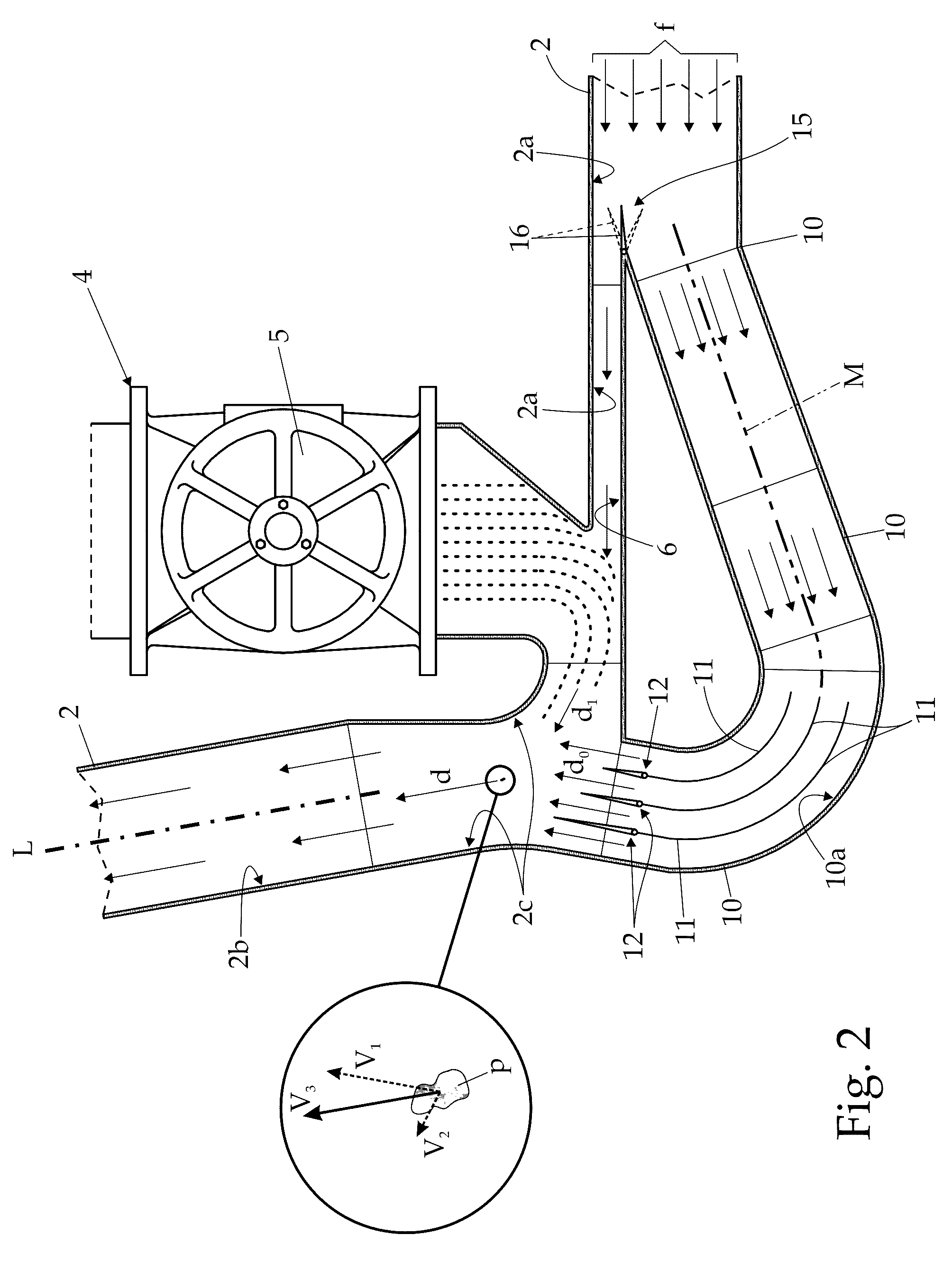
[0019]With reference to FIGS. 1 and 2, number 1 indicates as a whole a drying plant for particulate materials, which can be advantageously used for the rapid drying of cut tobacco.

[0020]The drying plant 1 firstly comprises a long drying duct 2 preferably with square or rectangular section, which is provided with a substantially rectilinear starting section 2a extending substantially parallel to the ground, i.e. horizontally; a final substantially rectilinear ascending section 2b extending upwards with an angle of inclination α with respect to the vertical preferably ranging between 0° and 30°; and an intermediate curved section 2c joining / connecting the rectilinear starting section 2a to the final rectilinear section 2b.

[0021]In the example shown, in particular, the final section 2b of the drying duct 2 has an angle of inclination α with respect to the vertical preferably, though not necessarily, equal to approximately 10°. Preferably the length of the final rectilinear section 2b ...


PUM


Abstract

Drying plant for particulate materials comprising: a drying duct which is provided with a substantially horizontal rectilinear starting section, a rectilinear ascending final section which extends upwards with a predetermined angle of inclination with respect to the vertical, and a curved intermediate section which connects the rectilinear starting section to the rectilinear final section; a hot gas generator designed for supplying to the inlet of the rectilinear starting section of the drying duct a flow of process gas at high temperature; a particulate feeding device which is structured so as to be able to feed / introduce into the rectilinear starting section of the drying duct a flow of particulate material to be dried substantially without relevant leaks of process gas from the drying duct; and a bypass duct which branches from the rectilinear starting section of the drying duct upstream of the particulate feeding device, and then re-joins the drying duct at the curved intermediate section, so as to feed back into the drying duct the process gas diverted inside it.

Description

CROSS-REFERENCE TO RELATED APPLICATIONS[0001]The present application claims priority under 35 U.S.C. §119 to Italian Patent Application No. TV2014A000053, filed Apr. 4, 2014, the entirety of which is incorporated herein by reference.FIELD OF THE INVENTION[0002]The present invention concerns a drying plant for particulate materials.[0003]More in detail the present invention concerns a drying plant for the rapid drying of cut tobacco, use to which the following description will make explicit reference without loss of generality.BACKGROUND OF THE INVENTION[0004]As is known, plants for the rapid drying of cut tobacco use a process gas with temperature higher than 200° C., to rapidly evaporate the water contained in the particles of cut tobacco.[0005]More in detail, the majority of these drying plants are provided with a long straight drying duct arranged vertically, traditionally called “drying column”, inside which a more or less constant flow of process gas is made to flow upwards wit...

Claims


Application Information

Patent Timeline
Patent Type & Authority Patents(United States)
IPC IPC(8): F26B3/08A24B3/04
CPCF26B3/08A24B3/04F26B2200/22A61G1/00A61G11/007A61G11/009F26B17/045F26B17/101F26B17/103
Inventor FAVARO, MANSUETO
Owner GARBUIO
Why Eureka
Try Eureka