Apparatus and method for moving catalyst bins

a technology of apparatus and catalyst bins, which is applied in the direction of hand carts, lifting devices, transportation and packaging, etc., can solve the problems of posing safety and health risks, difficult final placement of catalyst bins within the truck trailer, and insufficient room on the truck trailer to efficiently opera

Inactive Publication Date: 2016-12-20
TAYLOR KENNETH
View PDF47 Cites 36 Cited by
  • Summary
  • Abstract
  • Description
  • Claims
  • Application Information

AI Technical Summary

Benefits of technology

[0027]After the first and second idler roller assemblies are inserted to support the first end of the catalyst bin base, the first and second legs of the lifting jack are inserted within the second end of the catalyst container base. The lifting jack is then actuated to raise the load-bearing surface of the lifting jack, which in turn raises the second end of catalyst bin base for rolling support upon the rollers of the lifting jack. The first and second ends of the catalyst bin base are now supported upon rollers, facilitating movement of the catalyst bin.
[0028]Preferably, the lifting jack includes a wheeled truck that supports a hydraulic jack. A handle is preferably pivotally mounted to the wheeled truck for actuating the hydraulic jack and for steering movement of the lifting jack. The lifting jack also preferably includes a lift frame coupled to the wheeled truck and hydraulic jack, whereby actuation of the hydraulic jack operates to elevate the lift frame, including the first and second legs and the load-bearing surface of the lifting jack, which in turn raises the end of catalyst bin base with which the lifting jack is engaged. Preferably, as is true for most pallet jacks, actuation of the hydraulic jack causes the first and second legs of the lift frame to be raised relative to their respective load rollers.
[0030]In most conventional pallet jacks, the legs, or “forks”, of the pallet jack extend for 36 inches or more to position rollers at the extreme ends of such legs well toward the rear of the pallet to be raised. The length of such legs or “forks” generally exceeds the distance separating the outermost edges of the legs or “forks”. In contrast, in the preferred embodiment of the present invention, the distance between the outer sides, or outermost edges, of the first and second legs is actually greater than the length of each of the first and second legs. Once again, this helps to ensure that the insertion of the legs into the catalyst bin base will not risk any damage to the discharge nozzle that extends through the center of the catalyst bin base.
[0036]Preferably, the aforementioned method includes the further step of rotatably supporting the load-bearing surface relative to the pair of legs of the lifting jack for allowing the lifting jack to be rotated about a vertical axis relative to the load-bearing surface.

Problems solved by technology

After such catalyst beads have been used to process oil / gas mixtures, they are contaminated with hydrocarbon residue, and pose a safety and health risk.
However, once a catalyst bin has been loaded onto the rear end of the truck trailer by a forklift, final placement of each catalyst bin within the truck trailer is difficult, particularly due to the weight of loaded catalyst bins, and because the person or persons responsible for securing such catalyst bins within the truck trailer are working in relatively close quarters, particularly if one is trying to achieve relatively high packing density of catalyst bins within a truck trailer.
Typically, there is not enough room on the truck trailer to efficiently maneuver a forklift in order to place a loaded catalyst bin in a desired final location on the truck trailer.
The same issue is faced when the truck trailer has arrived at its destination, e.g., a catalyst reclamation treatment facility, and the catalyst bins must now be removed from the truck trailer.
Were one to attempt to insert such a pallet jack into the base of a catalyst bin, the forks of the pallet jack would impact the discharge hopper of the catalyst bin, preventing the forks from being fully inserted, and risking damage to the discharge hopper, with the additional risk of catalyst bead leakage.
However, the mechanism used to increase the spacing between the forks adds to the cost and complexity of the pallet jack.
Moreover, even if the forks of a pallet jack could be separated by a sufficient distance to avoid impacting upon the discharge nozzle of a catalyst bin, most pallet jacks lack the lifting capacity to lift a fully-loaded catalyst bin.
While some pallet jacks are capable of lifting and moving as much as 8,000 pounds, those pallet jacks are considerably more expensive than those designed to lift 5,500 pound loads.
However, even the shortest fork length illustrated by Meijer is not short enough to avoid damage to the discharge nozzle of a catalyst bin.
Incorporating permanently-deployed wheels or rollers within the catalyst bin itself is not a viable solution since such catalyst bins should not easily roll or otherwise move during transport.

Method used


Image

  • Apparatus and method for moving catalyst bins
  • Apparatus and method for moving catalyst bins
  • Apparatus and method for moving catalyst bins

Examples


Embodiment Construction

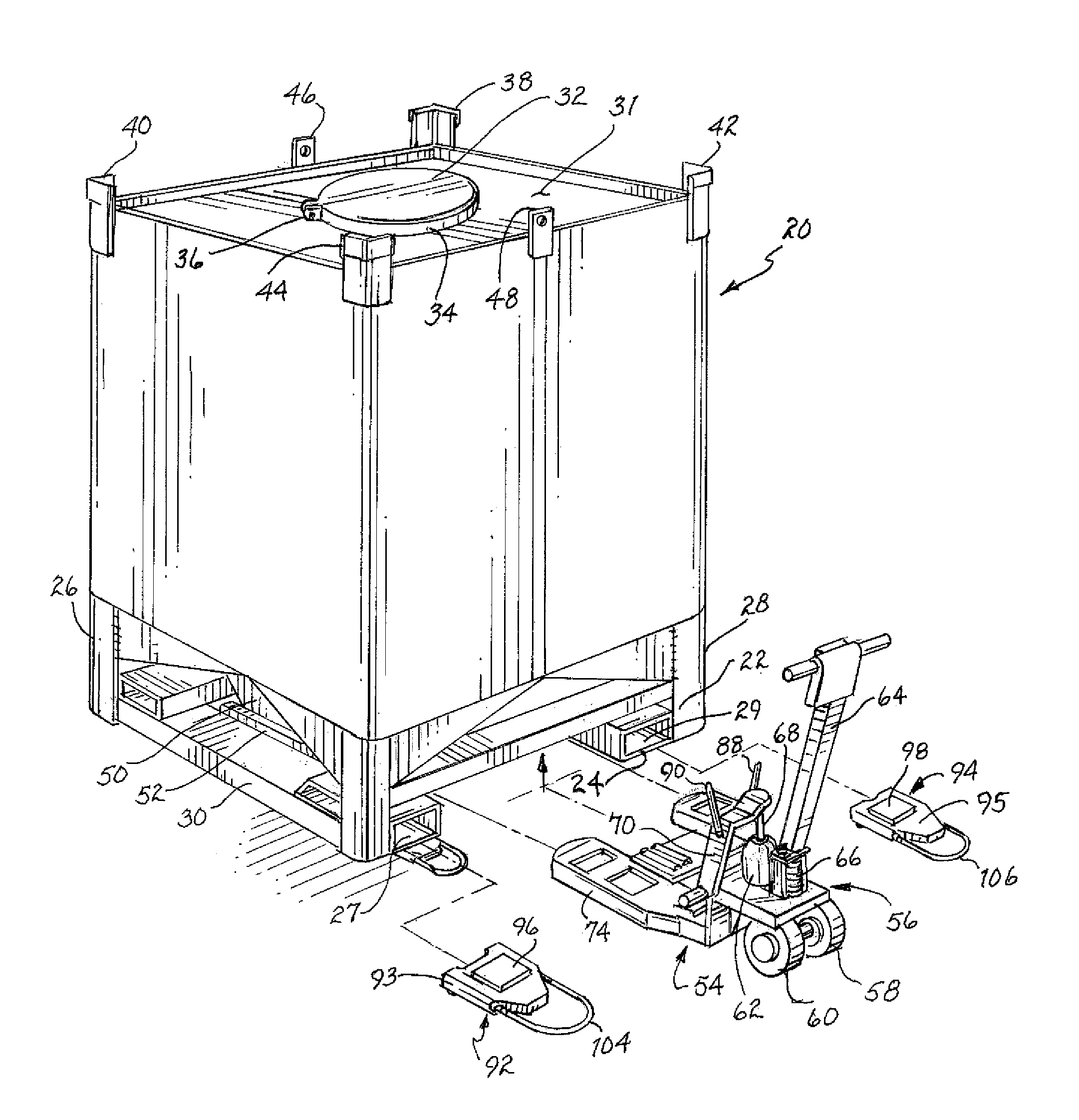
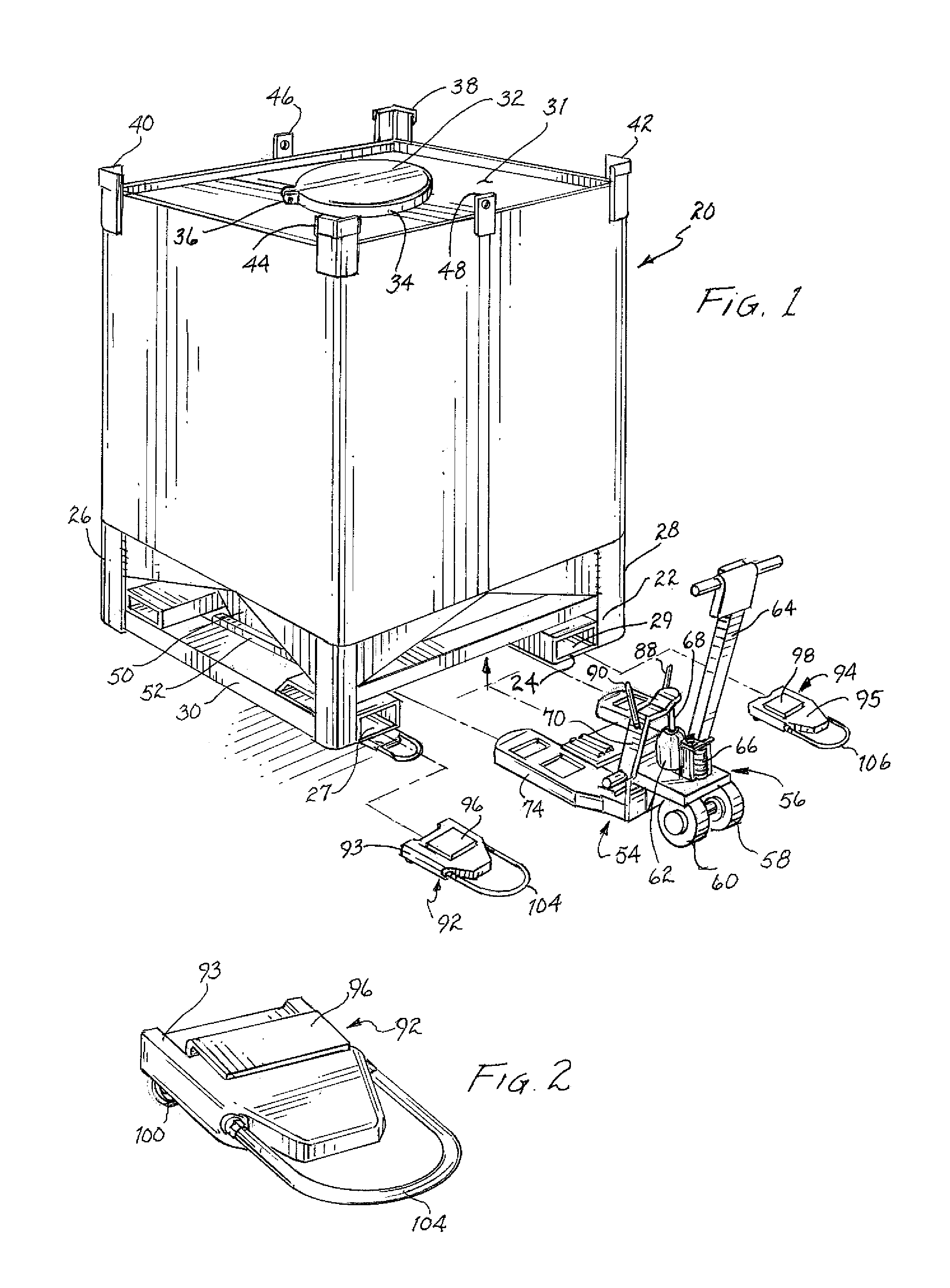
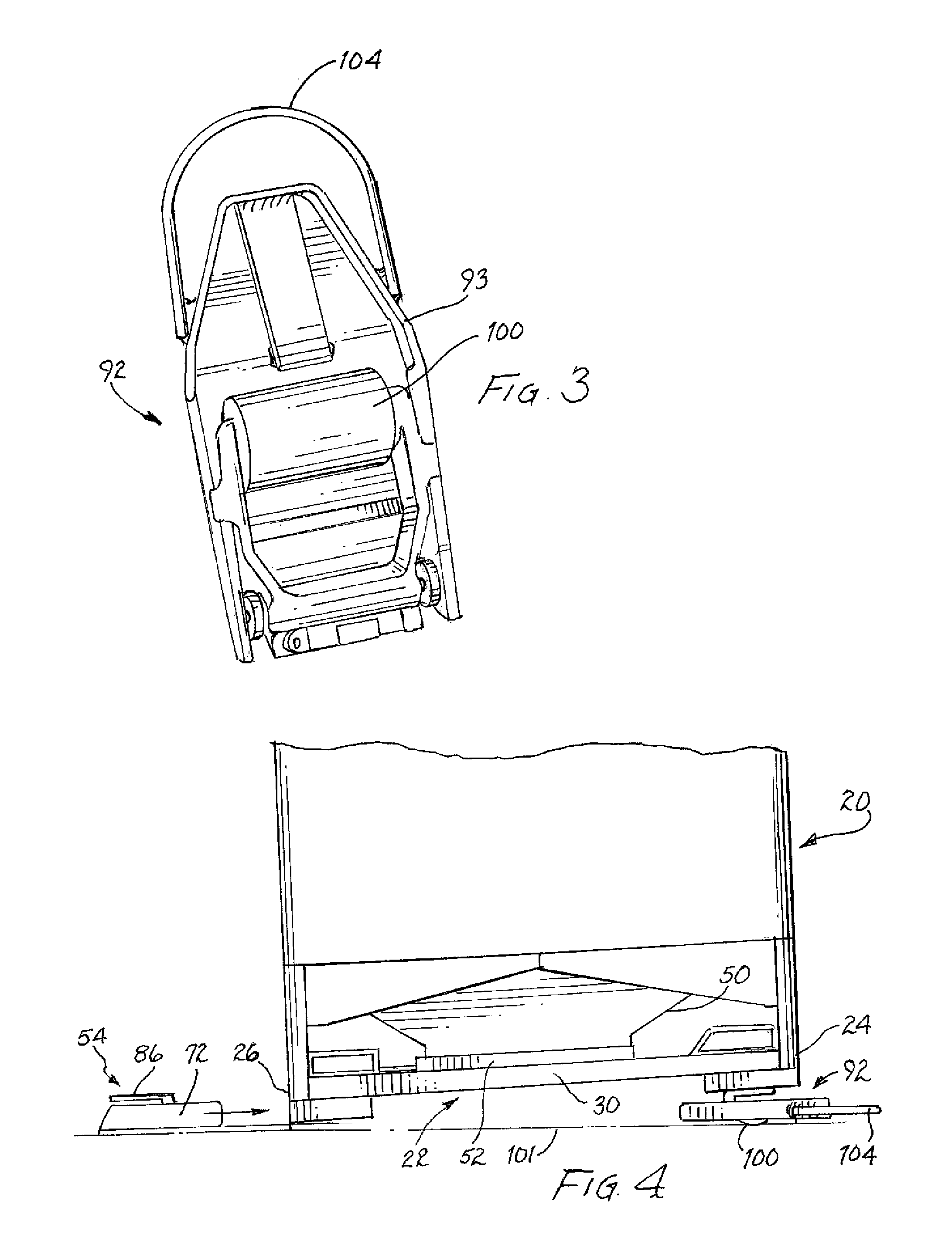
[0051]A typical catalyst bin, of the type used to haul spent catalyst beads in the oil fracking industry, is shown in FIG. 1, and is designated generally by reference numeral 20. Catalyst bin 20 is conventionally made of heavy gauge steel construction, and includes base 22 which extends between first end 24 and second, opposing end 26. Base 22 also includes first and second opposing sides 28 and 30, respectively. A pair of fork lift ports, or pockets, 27 and 29, are provided within base 22, extending along opposing sides 28 and 30, respectively, and extend fully through base 22 to opposing end 26; pockets 27 and 29 are adapted to receive the forks of a conventional fork lift for raising and moving catalyst bin 20 where circumstances permit.

[0052]Still referring to FIG. 1, the top 31 of catalyst bin 20 includes a filler opening (not visible) for loading material into the catalyst container. The filler opening is shown sealed by a cover 32 that is removably secured over the filler ope...


PUM


Abstract

Apparatus for moving catalyst containers includes a lifting jack having first and second legs each supporting a roller, and each having a relatively short length to avoid contact with the discharge hopper of the container. First and second idler rollers are inserted under one end of the container base. A load plate of the lifting jack is engaged with the second end of the container base, and raised, allowing the container to be moved. The load plate is rotatably supported by a support plate positioned between the legs of the lifting jack. In use, a first end of the base is raised, the idler rollers are inserted, the first end is lowered, the lifting jack is inserted into the second end of the base, and raised to permit transport of the container.

Description

BACKGROUND OF THE INVENTION[0001]1. Field of the Invention[0002]The present invention relates generally to apparatus and methods for moving containers, and more particularly, to an apparatus and method for adapted to move loaded catalyst bins within relatively close quarters.[0003]2. Description of the Relevant Art[0004]In the chemical and petrochemical industry, catalysts are often used to help process hydrocarbons like gas an oil. For example, catalysts are often used to accelerate the “cracking” of heavy gas oil into diesel oils and gasoline and / or kerosene.[0005]Recently, “fracking”, or hydraulic fracturing, has been used to a greater degree to recover natural gas and oil from deep rock formations of spent wellbores. In fracking, a slurry of water, sand and chemicals are injected under high pressure into a wellbore to create small fractures through which gas and oil can escape to the surface. Fracking can make recovery of such resources economically feasible in cases where other...

Claims


Application Information

Patent Timeline
Patent Type & Authority Patents(United States)
IPC IPC(8): B66F9/06B66F9/065B66F9/075B60B33/00
CPCB66F9/065B60B33/0002B66F9/0655B66F9/07504B66F9/07563B62B5/0086B62B3/0618B62B3/06
Inventor TAYLOR, KENNETH
Owner TAYLOR KENNETH
Why Eureka
Try Eureka