
Device for covering a building structure and structure covered by such a device

a technology for building structures and devices, applied in the direction of covering/linings, sheet joining, fastening means, etc., can solve the problems of affecting the longevity and appearance of the structure, affecting the integrity of the sheet, and affecting the structural integrity and protective qualities. , to achieve the effect of economic and mechanical efficiency

Inactive Publication Date: 2016-12-20
BACACIER 3 S
View PDF14 Cites 7 Cited by
  • Summary
  • Abstract
  • Description
  • Claims
  • Application Information

AI Technical Summary

Benefits of technology

The invention offers a cost-effective and mechanically efficient solution for covering structures with covering sheets. It allows for the ability to change the visual aspect or functional properties of the covering sheet after installation without compromising the physical integrity of the sheet or the quality of the attachment to the structure. This is made possible by utilizing fastening attachments that form part of the covering sheet, which can be easily detached and re-attached without affecting the attachment of the sheet to the structure. The system also allows for the addition of accessories and modifications to be made without drilling or intrusive operations, facilitating the modification of the appearance of the structure while maintaining the integrity of the attachment of the sheet on to the structure.

Problems solved by technology

However, once the covering is in place, it remains there for periods that can be fairly long, often over several decades without it being possible for any substantial change in the appearance or functions thereof to be made at the risk of altering the structural integrity and protective qualities, in particular the sealing tightness or weather resistance thereof.
These drilled holes contribute to degrading the integrity of the sheets in which they have been borne and affect their longevity and appearance over time.
This deficiency is further compounded when the elements added are to be dismantled in order for them to be replaced by others that require drilling new holes.
Thus the existing systems are afflicted by a dual limitation or deficiency.
On the one hand they do not allow for the possibility of easily implementing coverings with variations in appearance or multiple motifs or patterns in each surface covered, independently of the constraints imposed by the undiversified configuration of the sheets available and by the needs linked to their overlapping on the edge.
On the other hand, they have very poor capacity to support the addition of detachable elements that are likely to be modified or moved one or more times during the useful life of the constructed structure covered.
However, on account of the snap action connection, the overall strength and resilience and the stability of this solution remain limited, unless provisions are made for some expensive adjustments or modifications.

Method used


Image

  • Device for covering a building structure and structure covered by such a device
  • Device for covering a building structure and structure covered by such a device
  • Device for covering a building structure and structure covered by such a device

Examples


Embodiment Construction

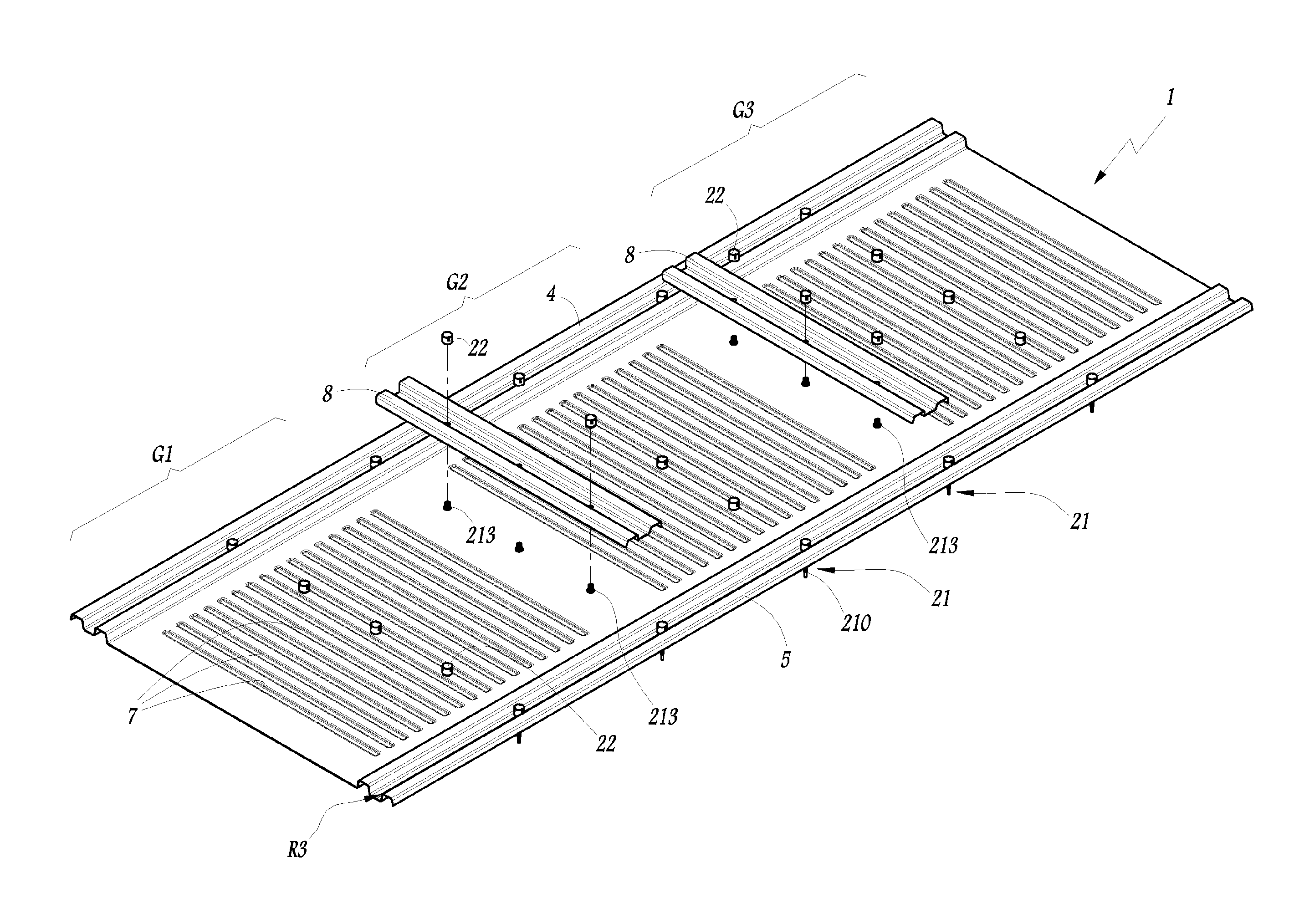
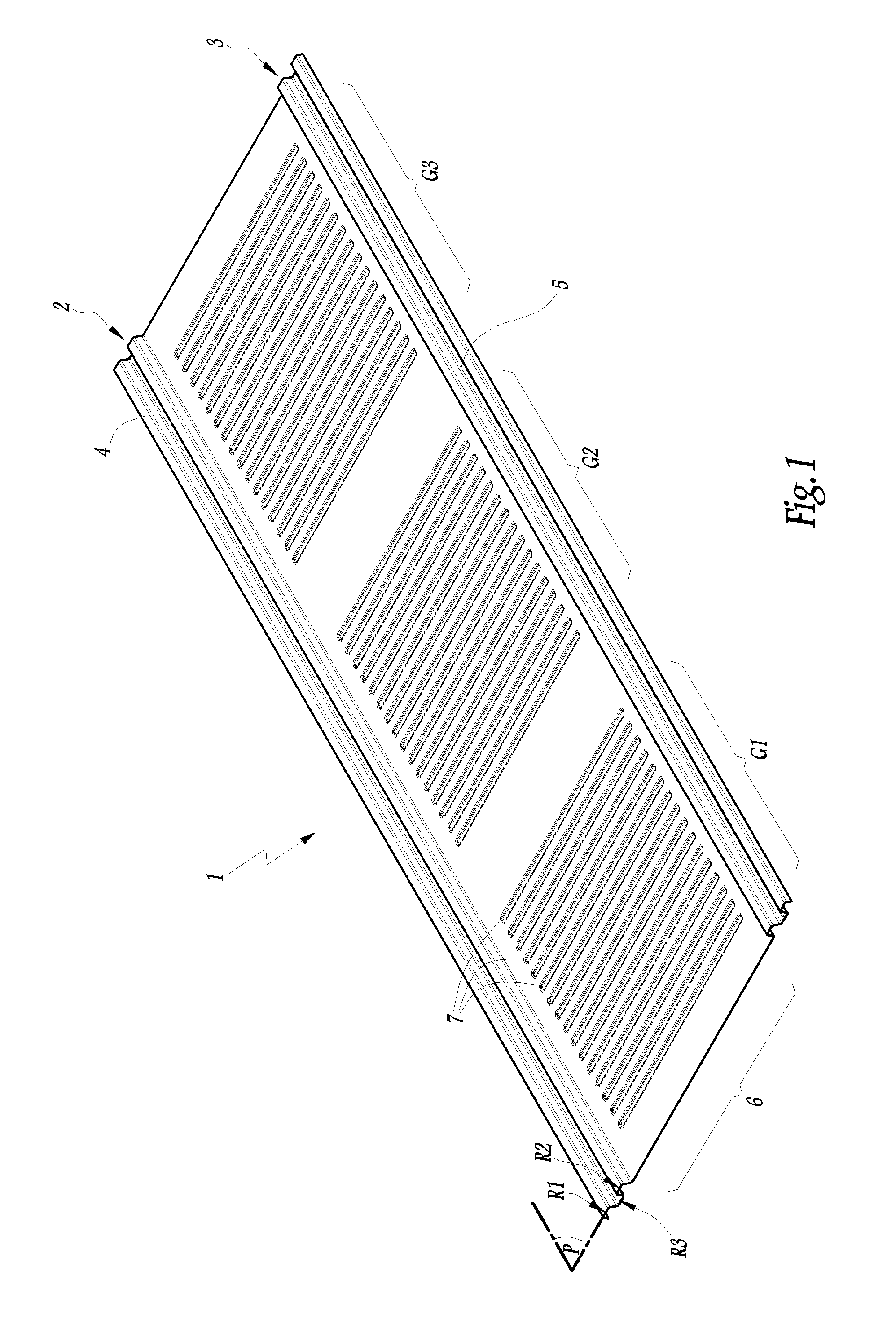
[0038]FIG. 1 illustrates a metal sheet 1 of rectangular shape, provided on two parallel edges 2, 3, defining the length of the sheet 1, with ribs 4 and 5 that are parallel and open. These ribs 4, 5 have in cross section, a double S shaped form. In other words, they have, in cross section, two reliefs R1, R2 located above a median plane P of the sheet 1, on either side of a relief R3 located below the median plane P, looking at FIG. 1. By way of a variant, the ribs have a different form, as shown, by way of a non limiting example, in FIG. 16 in which the corresponding sheet and its ribs are respectively referenced as 1′, 4′ and 5′.

[0039]The ribs 4, 5 of the sheet 1 here are constituent elements of the edges 2, 3. By way of a variant, they are arranged along the width of the sheet. In another variant embodiment, the ribs 4, 5 do not define the edges of the sheet but occupy the central portion of the latter. In other embodiments, the sheet may be square in shape.

[0040]In FIG. 1, the sp...


PUM


Abstract

The invention relates to a covering device comprising: at least one metal sheet, especially a metal sheet used for cladding, suitable for covering at least one section of a surface of a building structure, fastenings for definitively attaching the metal sheet to the structure, at least one accessory suitable for applying to a receiving area on the metal sheet, and means for removably attaching the accessory to the receiving area, that are suitable for attaching the accessory once the metal sheet is already attached to the structure by means of the fastenings, maintaining the structural integrity of the metal sheet, and also the integrity, especially in terms of tightness, of the attachment of the metal sheet to the structure by means of the fastenings, said attaching means including a head of the fastenings, that can enable the assembly, and if need be, the disassembly, of the accessory, without affecting the attachment of the metal sheet to the structure by means of the fastenings.

Description

CROSS-REFERENCE TO RELATED APPLICATIONS[0001]This application is the U.S. National Phase under 35. U.S.C. §371 of International Application PCT / EP2013 / 058767, filed Apr. 26, 2013, which claims priority to French Patent Application No. 1253947, filed Apr. 27, 2012. The disclosures of the above-described applications are hereby incorporated by reference in their entirety.[0002]The invention relates to a device for covering walls in a built structure, of the type referred to as the cladding system commonly used in buildings. In such a system one or more exterior surfaces of the building are covered with panels or facing sheets, known as cladding sheets. These sheets are attached to elements that form part of the supporting structure of the building or that are attached on to this structure.BACKGROUND OF THE INVENTION[0003]The term structure here is used to refer to a structural framework, for example made out of metal profiles or the continuous face of an interior or exterior wall, mad...

Claims


Application Information

Patent Timeline
IPC IPC(8): E04F13/12E04F13/08F16B5/02
CPCE04F13/0832E04F13/0837E04F13/0862E04F13/0871E04F13/12E04F13/0801F16B5/0275E04F13/08
Inventor VIGOUROUX, JEAN-CHRISTOPHEFAISANDIER, JULIENBERTRAND, JOFFREY
Owner BACACIER 3 S
Learn More