
System and method for controlling the position of a movable object on a viewing device

a technology of a viewing device and a control system, which is applied in the direction of instruments, aircraft components, electric digital data processing, etc., can solve the problems of limited speed of moving the cursor using the trackball, slow mode of moving the cursor from one display to another, and not always easy for the pilot to find it immediately, so as to achieve quick and effective positioning of objects

Active Publication Date: 2016-12-27
DASSAULT AVIATION
View PDF6 Cites 2 Cited by
  • Summary
  • Abstract
  • Description
  • Claims
  • Application Information

AI Technical Summary

Benefits of technology

The invention proposes a control system for an aircraft cockpit that allows quick and effective positioning of an object on a viewing device without the limitations of previous designs.

Problems solved by technology

It also makes it possible to move the cursor from one display to another, but this mode of moving the cursor from one display to another is generally slow.
However, although the cursor is thus specifically identified when it is reactivated, it is not always easy for the pilot to find it immediately.
Furthermore, moving the cursor using the trackball is limited in terms of speed.
Thus, the time the pilot spends locating the cursor or moving it on the display is lost time during which the pilot is not available to perform the tasks for which he is responsible.
The use of the cursor being the favored method of interacting with the systems, this time may be significant, in particular over a long flight time.
Moreover, this method of controlling the position of the cursor does not work if the aircraft is equipped with a small number of large displays, or even a single display.
In fact, the assignment command of the cursor on a specific display is then meaningless, and the path to be traveled by the cursor between two remote points of a single display it makes the entire concept of interaction not very viable during operational use.

Method used


Image

  • System and method for controlling the position of a movable object on a viewing device
  • System and method for controlling the position of a movable object on a viewing device
  • System and method for controlling the position of a movable object on a viewing device

Examples


Embodiment Construction

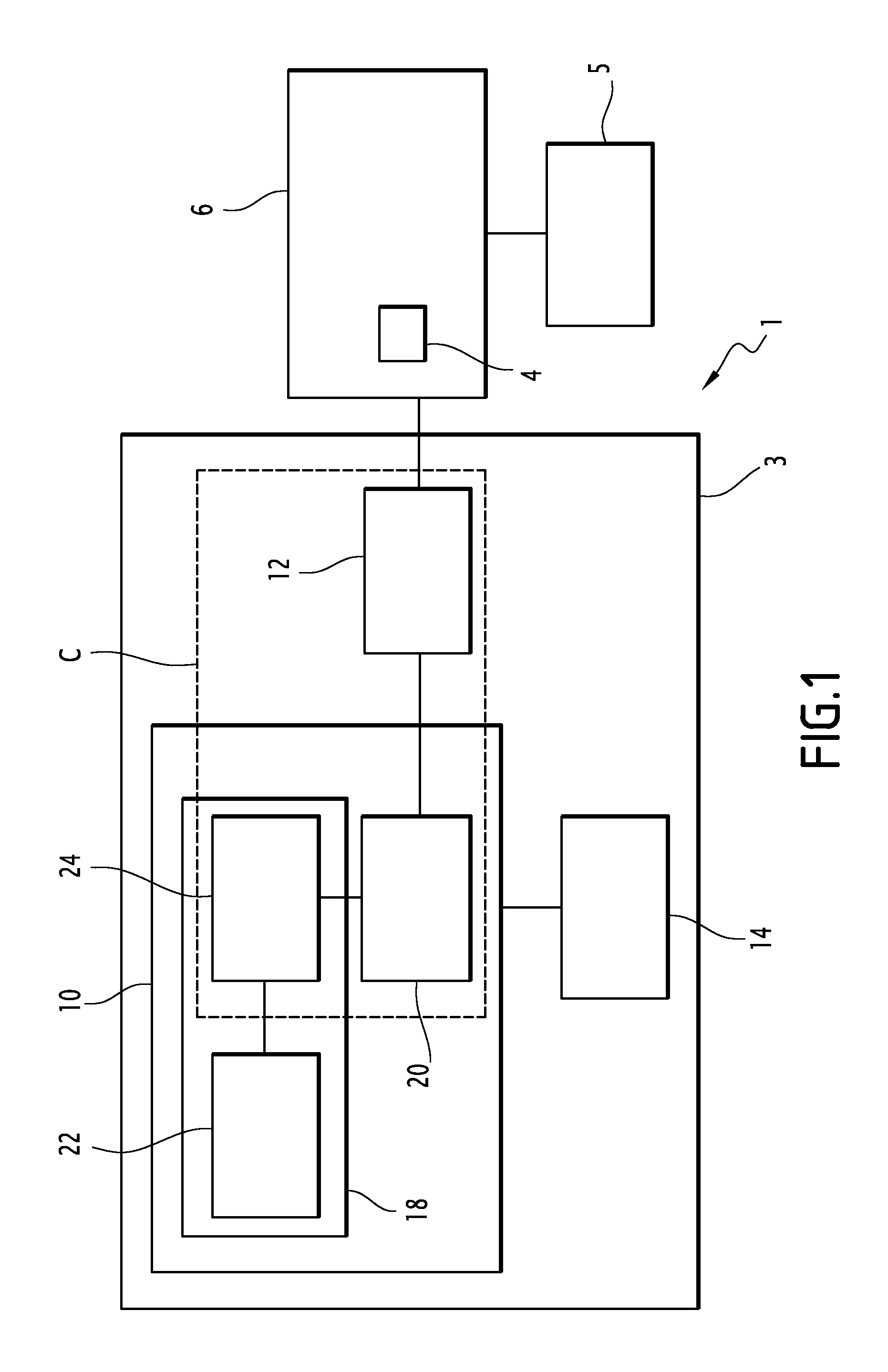
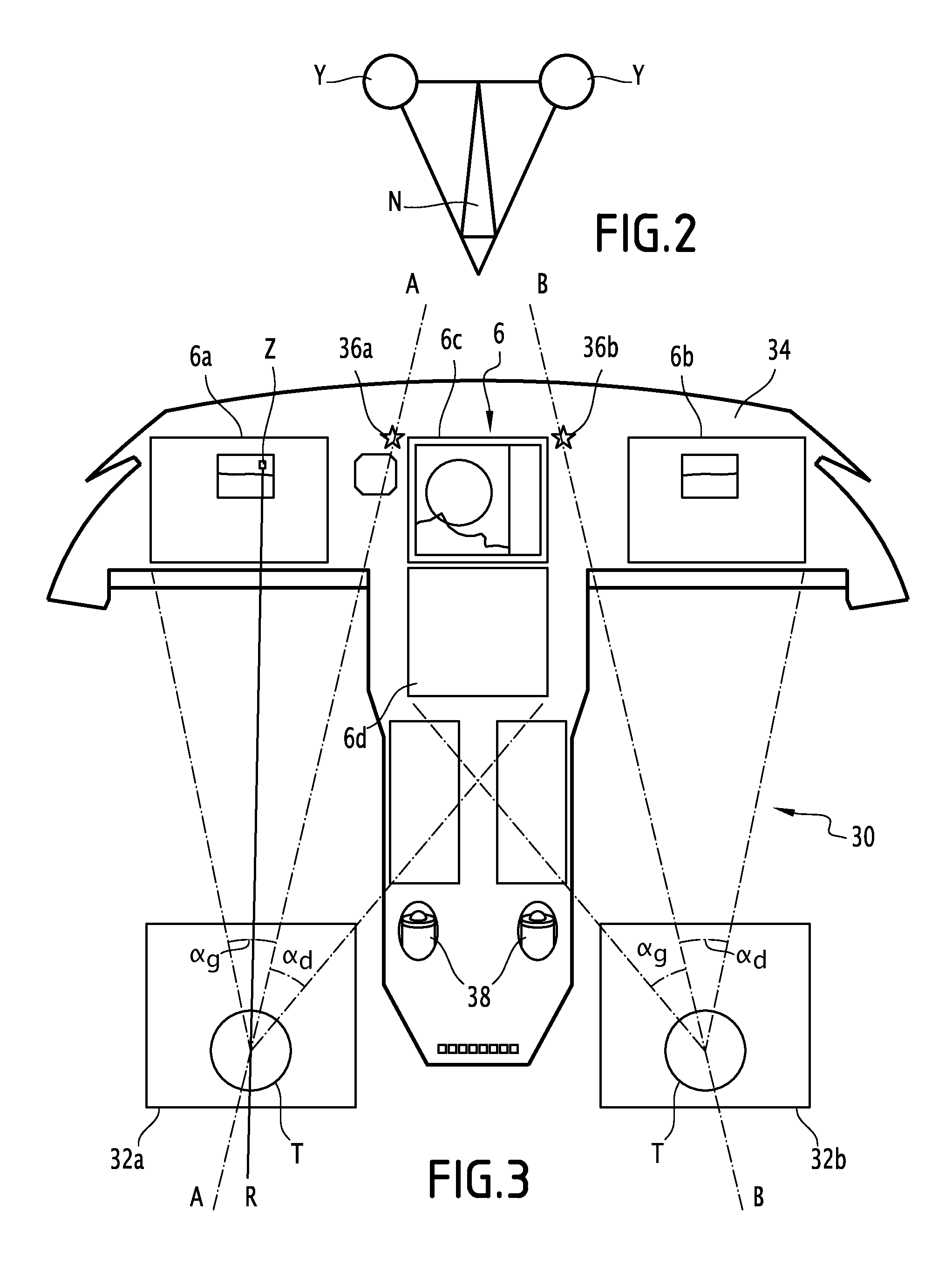
[0056]FIG. 1 diagrammatically shows a system 1 according to the invention, for an operator, in particular a pilot, to control a movable object 4 such as a cursor on a viewing device 6 positioned in the cockpit of an aircraft.

[0057]The viewing device for example comprises several displays on which the cursor 4 can move, in response to an action by the operator on the control system 1.

[0058]The control system 1 comprises visual control means 3 for controlling the position of the cursor 4, adapted for positioning and moving the cursor 4 over a zone of the viewing device 6 targeted by the pilot's gaze.

[0059]The system 1 also comprises manual control means 5 for controlling the position of the cursor 4, adapted for moving the cursor on the viewing device 6 in response to a manual action by the operator.

[0060]The visual control means 3 comprise an input module 10 for the gaze, adapted for determining, at least at one given moment, the position of the target zone targeted by the operator's...


PUM


Abstract

A system for controlling the position of a movable object on a viewing device in an aircraft cockpit, which can be actuated by an operator includes means for determining, at least at one given moment, a position of a target zone on said viewing device toward which the operator's gaze is directed, and positioning means adapted for placing the object on the target zone of the viewing device.

Description

BACKGROUND OF THE INVENTION[0001]Field of the Invention[0002]The present invention relates to a system for controlling a position of a movable object on a viewing device in an aircraft cockpit, said system being configured to be actuated by an operator.[0003]It in particular applies to the positioning of a cursor on the viewing displays positioned in the cockpit of the aircraft.[0004]Description of the Related Art[0005]Within the cockpit, such viewing displays allow pilots to interact with the airplane systems. This interaction is traditionally done using cursors, which are piloted using a dedicated control device of the mouse type.[0006]Each pilot thus has access to a cursor control device (CCD), comprising a trackball that can be actuated by the pilot to move the cursor, as well as buttons allowing the pilot, once the cursor is positioned in the desired zone, to modify or insert values, or to make selections.[0007]Rotating the trackball makes it possible to move the cursor on each...

Claims


Application Information

Patent Timeline
Patent Type & Authority Patents(United States)
IPC IPC(8): G06F3/01G06F3/147B64D43/00G06F3/0354G06F3/0481
CPCG06F3/013B64D43/00G06F3/012G06F3/03549G06F3/04812G06F3/147G09G2380/12
Inventor SAINT-REQUIER, CYRILKERVELLA, AUDREN
Owner DASSAULT AVIATION
Learn More