Casting mold

a technology of casting die and mold, which is applied in the direction of manufacturing tools, foundry moulding apparatus, foundry patterns, etc., to achieve the effects of increasing the dimensional accuracy of cast products, and reducing the number of parts

Active Publication Date: 2017-01-03
HONDA MOTOR CO LTD
View PDF10 Cites 0 Cited by
  • Summary
  • Abstract
  • Description
  • Claims
  • Application Information

AI Technical Summary

Benefits of technology

[0005]It is an object of the present invention to provide a casting die assembly, which is relatively low in cost and weight, is highly versatile in use, and prevents burrs from being produced on cast products.
[0022]With the casting die assembly according to the present invention, when the first die and the second die are combined, the pressure applied by the pressure boosting unit to the cavity die through the support is increased, thereby minimizing burrs on the cast product. Since the base, which serves as a main die body, is shaped as a plate, it is possible to reduce the manufacturing cost and weight of the casting die assembly, and the casting die assembly can be made versatile in use.

Problems solved by technology

The gap allows molten metal that is poured into the cavity to leak out, thereby producing a phenomenon called “metal spits” that is liable to produce burrs on the cast product.

Method used


Image

  • Casting mold
  • Casting mold
  • Casting mold

Examples


first embodiment

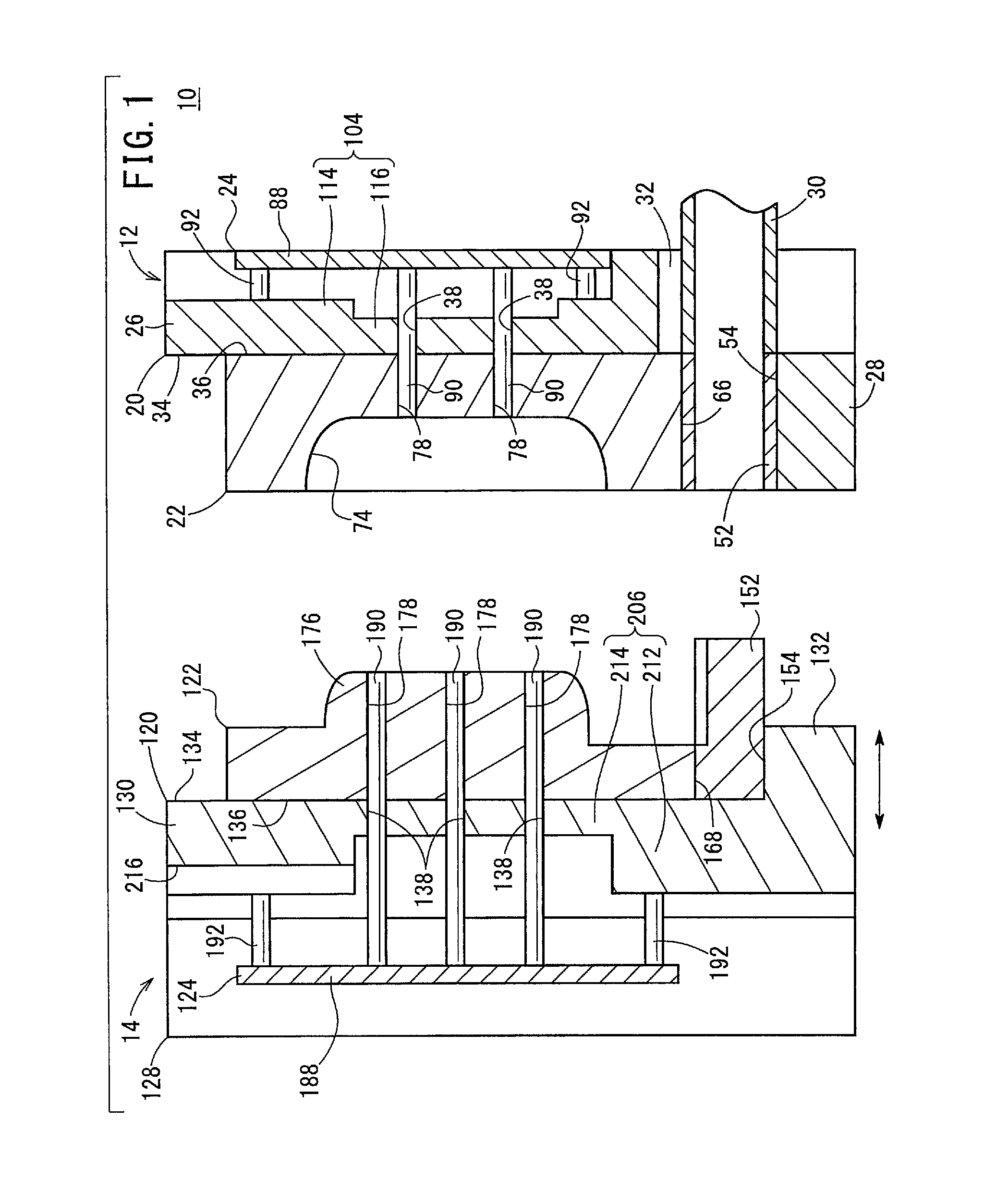
[0041]Firstly, a casting die assembly 10 according to a first embodiment of the present invention will be described below. The casting die assembly 10 is a die assembly for use in a die casting process. Further, as shown in FIG. 1, the casting die assembly 10 includes a fixed die (first die) 12 and a movable die (second die) 14, which face each other and are movable toward and away from each other, and a slide die 16 and a slide mechanism 18 (see FIG. 7), which are mounted on the movable die 14. Upon closure of the casting die assembly 10, the fixed die 12, the movable die 14, and the slide die 16 jointly define a cavity C (see FIG. 12), which is complementary in shape to a cast product.

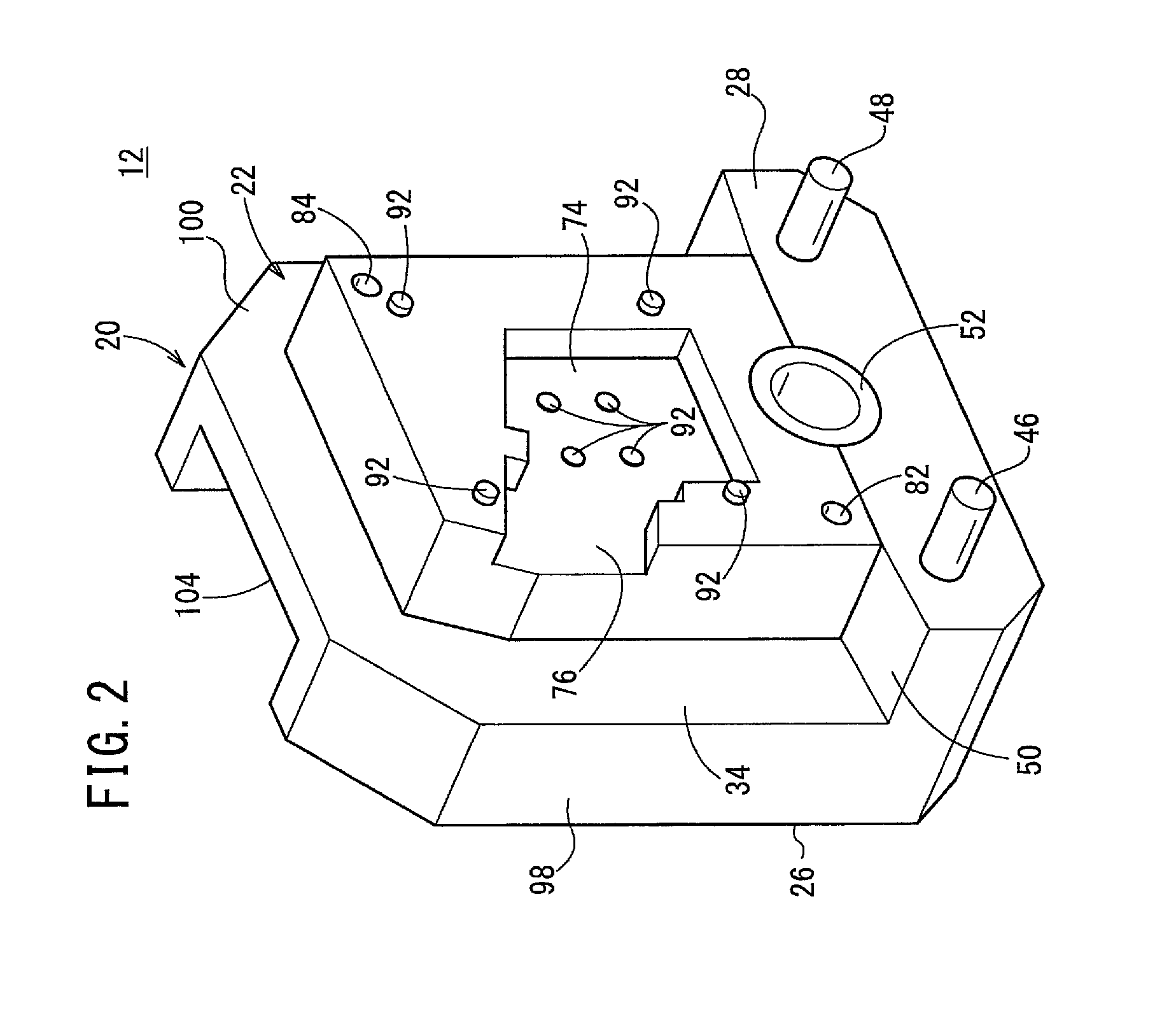
[0042]First, structural details of the fixed die 12 will be described below. As shown in FIGS. 1 through 4, the fixed die 12 has a main fixed die body 20, a fixed cavity die 22 constructed from a plate mounted on the main fixed die body 20, and an ejector mechanism 24 for ejecting a cast product out ...

second embodiment

[0102]A casting die assembly 10A according to a second embodiment of the present invention will be described below with reference to FIGS. 14 through 17. Parts of the casting die assembly 10A according to the second embodiment, which are identical to those of the casting die assembly 10 according to the first embodiment, are denoted by identical reference characters, and such features will not be described in detail below.

[0103]As shown in FIGS. 14 through 16, the casting die assembly 10A according to the second embodiment includes a fixed die (first die) 12a and a movable die (second die) 14a. The fixed die 12a has a main fixed die body 20a including a base 26a. The base 26a includes an attachment plate 302 having a square hole (pressure boosting unit) 300 defined therein, which is provided instead of the thin-walled panel 116 described above, and a main attachment plate body (support) 114. The hole 300 is of a size that is large enough for the ejector pins 90 to be inserted therei...


PUM

PropertyMeasurementUnit
widthaaaaaaaaaa
pressureaaaaaaaaaa
thickaaaaaaaaaa

Abstract

Provided is a highly versatile casting mold in which weight and manufacturing cost can be reduced, and whereby flash can be suppressed. A plate-shaped base part having a flat attachment face to which a back face of a fixed-cavity mold is attached is provided to a fixed mold constituting a casting mold. A portion of the base part in contact with the back face of the fixed-cavity mold has an attachment part body for supporting the fixed-cavity mold, and a pressure increasing means for increasing the pressure imparted to the fixed-cavity mold via the attachment part body in a state in which the mold is closed.

Description

TECHNICAL FIELD[0001]The present invention relates to a casting die assembly (casting mold) including a plate-shaped base having a flat attachment surface to which the rear surface of a cavity die is attached.BACKGROUND ART[0002]One known type of casting die assembly is made up from a fixed die and a movable die, each having a thick die block with a recess defined therein, and a cavity die that is fitted in the recess (see FIG. 5 of Japanese Laid-Open Patent Publication No. 61-226159). The casting die assembly is highly costly to manufacture because it is necessary to bore the recess highly precisely. The casting die assembly also is problematic in that it is heavy, since the die block with the recess defined therein is thick. Further, the casting die assembly is not versatile in use, due to the fact that the cavity die and the recess must be complementary in shape to each other.[0003]To solve the aforementioned problems, there has been proposed a casting die assembly including dies...

Claims


Application Information

Patent Timeline
Patent Type & Authority Patents(United States)
IPC IPC(8): B22D17/22B22C9/06B22D17/20
CPCB22D17/22B22C9/06B22D17/2015B22D17/2227B22D17/2236
Inventor YOKOYAMA, KUNIHIROMATSUSHITA, HIROSHIHIGASHI, TAKAYUKIFUJITA, HIROMIMASUBUCHI, MASANORIKATAHIRA, KENICHIKUBO, YOSHINORINIWA, TAKANORI
Owner HONDA MOTOR CO LTD
Why Eureka
Try Eureka