Highly sensitive imaging camera for space applications including detection of ultrahigh energy cosmic rays

a high-sensitivity, cosmic ray technology, applied in the field of imaging cameras for detecting ultra-high-energy cosmic rays in space, can solve the problems of large dead area around sensitive pixels, non-uniform response, low quantum efficiency, etc., and achieves low weight and cost, negligible dead area, and simple construction

Active Publication Date: 2005-10-18
RGT UNIV OF CALIFORNIA
View PDF8 Cites 1 Cited by
  • Summary
  • Abstract
  • Description
  • Claims
  • Application Information

AI Technical Summary

Benefits of technology

[0019]The present invention pertains to a photocathode camera for use in space that exhibits low weight and cost, has negligible dead area, is relatively simple to construct, and exhibits high quantum efficiency.
[0020]An aspect of the invention is to avoid the heavy structural vacuum-sealing elements typically involved in camera construction, as well as partial usage of vacuum in space. By way of example, and not of limitation, the camera is constructed in an inert gas atmosphere on the Earth at atmospheric pressure. The inert atmosphere can protect the photocathode surface from harmful gases. In some cases, in addition, a special protective layer may be applied over the photocathode, such as a thin layer of Arsenic. Once the camera reaches its operational orbit, the camera is vented and exposed to ultra high vacuum in space, then isolated from the space environment, and internally vacuum pumped with the excessive use of getter surfaces. The camera will be ready for use, and in some cases certain remaining processes in photocathode preparation may still be performed in space.
[0025]A still further aspect of the invention is to provide a Fresnel optical lens modified to perform simultaneously as an electron lens, without adverse effect on optical properties.
[0026]An object of the invention is to provide a detector which would become of key importance for any future space-borne EECR mission. Another object of the invention is to avoid deficiencies found in PMT cameras such as use of a transmission-mode photocathode, use of massive and bulky vacuum enclosures, use of expensive dynode multipliers, large dead area, and the extremely large number of PMTs needed to cover the focal plane, accompanied with readout electronics distributed all over that plane behind the PMTs. A further object of the invention is to provide a camera that uses a reflection-mode photocathode, does not require any vacuum chambers, does not require a dynode multiplier, does not have a dead area, uses only one super-large phototube, and uses a single, small, multi-pixel photoelectron sensor that can be integrated with a digital readout.

Problems solved by technology

One of the most challenging issues in Astroparticle Physics has been the observation of Extreme Energy Cosmic Rays (EECRs).
Apart from being heavy and complicated for space applications, such cameras can have other problems, like low quantum efficiency, in particular in the important ultraviolet region, very large dead area around sensitive pixels, non-uniform response, and high cost.
The origin of these cosmic rays presents a complete mystery, since they should not be able to arrive from large distances (due to the interaction with the low-energy photon background), and on the other hand there is no candidate for the “accelerator” of such particles nearby, or in fact, anywhere.
Although in principle feasible, this concept is hampered by numerous weaknesses.
Apart from the large mass and immense constructional complexity, such cameras can have an important scientific drawback, e.g., low sensitivity, and consequently relatively high detection threshold energy, and poor energy resolution.
Other drawbacks include very low quantum efficiency (in particular in the important ultraviolet region), very large dead area around the sensitive pixels, and very high cost.
It happens that PMTs present the main source of these problems.
However, so far no imaging phototubes based on a reflection-mode photocathode exist, with the exception of the Blind-HPD in which a blind resembling a Venetian blind is attached to the entrance window of the tube (see, D. Ferenc, Imaging Hybrid Photon Detectors with a Reflective Photocathode, Nucl. Instr. and Meth.
That design offers good imaging quality, but has only very limited application due to its narrow angular acceptance and wide time jitter.
It will also be appreciated that an imaging electron lens based on a reflection-mode photocathode is problematic in general because the photoelectrons must move in the opposite direction from the incoming light, which requires the focusing electrodes and the position-sensitive electron sensor to reside upstream from the photocathode.
This in turn leads to an unacceptable but apparently inevitable optical obstruction of the photocathode.

Method used


Image

  • Highly sensitive imaging camera for space applications including detection of ultrahigh energy cosmic rays
  • Highly sensitive imaging camera for space applications including detection of ultrahigh energy cosmic rays
  • Highly sensitive imaging camera for space applications including detection of ultrahigh energy cosmic rays

Examples


Embodiment Construction

[0036]Referring more specifically to the drawings, for illustrative purposes the present invention is embodied in the apparatus generally shown in FIG. 3 through FIG. 5. It will be appreciated that the apparatus may vary as to configuration and as to details of the parts, and that the method may vary as to the specific steps and sequence, without departing from the basic concepts as disclosed herein.

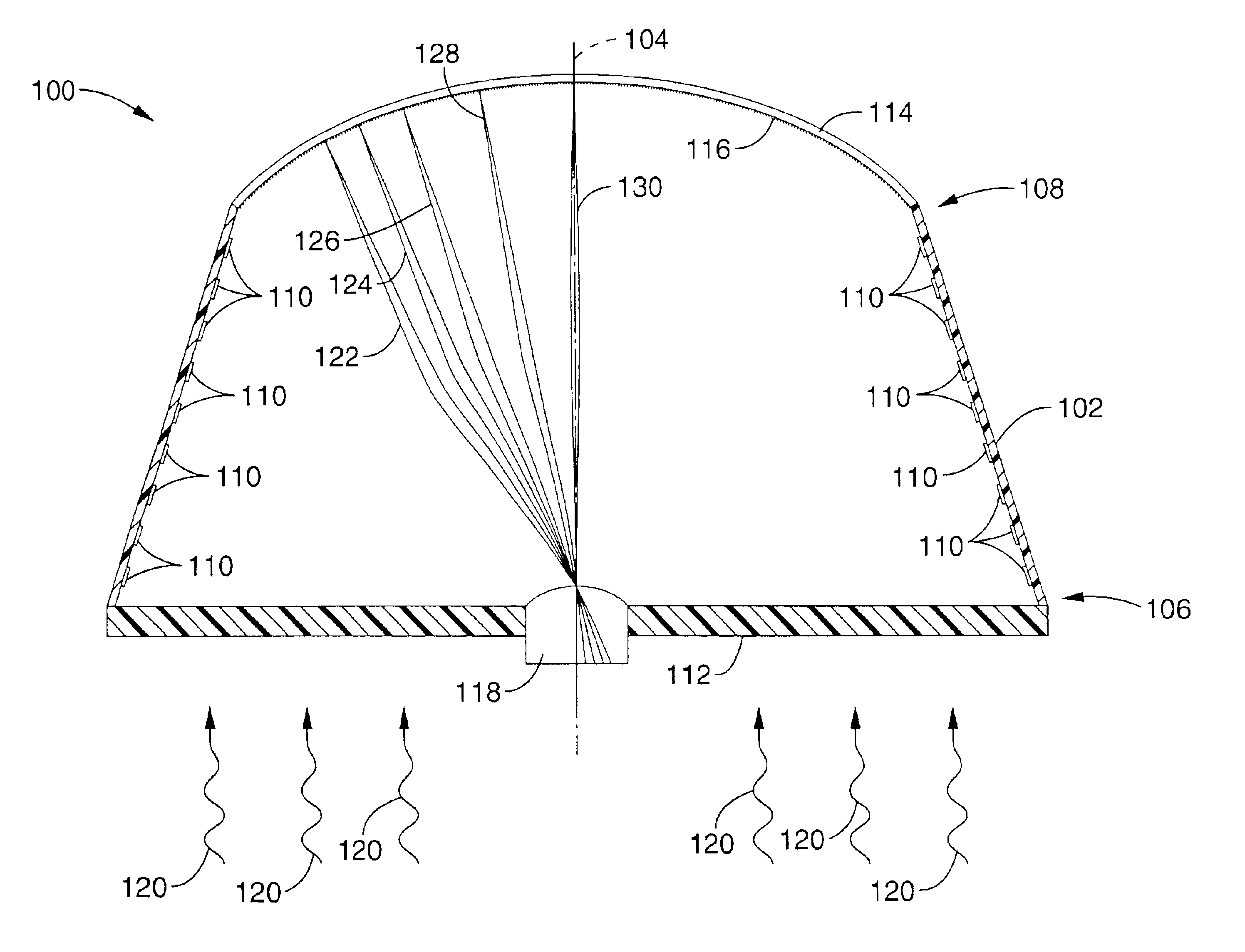
[0037]Referring first to FIG. 3, an embodiment of an imaging camera according to the present invention is shown and is generally designated 100. As will be seen, the present invention comprises an imaging electron lens that works with a reflection-mode photocathode. Its purpose is to focus photoelectrons emerging from a photocathode surface to a multi-pixel electron sensor.

[0038]In the embodiment shown, the imaging camera 100 includes a generally frusto-conical housing 102 that defines a central axis 104. The housing 102 further defines a proximal end 106 and a distal end 108. In a prefe...


PUM


Abstract

An imaging camera includes a housing that defines a proximal end and a distal end. A Fresnel lens is installed in the proximal end of the housing. Moreover, a reflection mode photocathode is installed in the distal end of the housing opposite the Fresnel lens. An electron sensor is disposed in the center of the Fresnel lens. A conductive layer is disposed on the interior of the housing. Further, the Fresnel lens establishes plural concentric optically passive surfaces that are parallel to a central axis defined by the imaging camera. A conductive layer is disposed on each optically passive surface, and an electron lens is established by the conductive layer on the interior of the housing and the conductive layers on the Fresnel lens.

Description

CROSS-REFERENCE TO RELATED APPLICATIONS[0001]This application claims priority from U.S. provisional application Ser. No. 60 / 386,984 filed on Jun. 6, 2002, incorporated herein by reference.STATEMENT REGARDING FEDERALLY SPONSORED RESEARCH OR DEVELOPMENT[0002]Not ApplicableINCORPORATION-BY-REFERENCE OF MATERIAL SUBMITTED ON A COMPACT DISC[0003]Not ApplicableBACKGROUND OF THE INVENTION[0004]1. Field of the Invention[0005]This invention pertains generally to imaging devices, and more particularly to imaging cameras for detecting ultrahigh energy cosmic rays in space.[0006]2. Description of Related Art[0007]One of the most challenging issues in Astroparticle Physics has been the observation of Extreme Energy Cosmic Rays (EECRs). The existence of particles with energy above ˜5×10¹⁹ eV raises fundamental questions about their origin and propagation in space. EECRs have been detected through the Extensive Air Showers (EAS) produced in the Earth Atmosphere. The shower development is accompani...

Claims


Application Information

Patent Timeline
Patent Type & Authority Patents(United States)
IPC IPC(8): G01J1/00G01T1/24G01T1/00H01J40/14H01J40/00H01L25/00H01L27/00H01J9/24H01J29/89H01J31/49H04NH04N5/225
CPCH01J9/244H01J29/894H01J31/49H04N5/225H04N23/00
Inventor FERENC, DANIEL
Owner RGT UNIV OF CALIFORNIA
Why Eureka
Try Eureka