Mooring Pull-In System

Active Publication Date: 2009-01-15
ADVANCED PRODUCTION AND LOADING AS
View PDF10 Cites 0 Cited by
  • Summary
  • Abstract
  • Description
  • Claims
  • Application Information

AI Technical Summary

Benefits of technology

[0006]The tension of the anchoring lines during connection and as anchored, is typically 10-250 tons, preferably 50-100 tons. During pull-in the tension can for one or more anchoring lines temporarily be released. The anchoring line can be prepared from wire, chain, polyester, Kevlar, other polymers, or the anchoring line can be a composite construction. Preferably, the anchoring line along the substantial length thereof is prepared from polyester, because of low weight and cost, and convenient elasticity. Preferably, at least one swivel is arranged at the coupling part, which simplifies correct orientation around the longitudinal axis of the anchoring line of the locking pin or similar. Preferably, at least one locking means is arranged for each crib, for example in the form of a locking pin that hinders that the coupling part can be released from the crib. Preferably, a fastening means for a pulling wire is arranged in each coupling part. Further, a device is preferably arranged for tightening or adjustment of length of the anchoring line, for example ±2 m, which for example is in the form of a releasable, position adjustable fastening for the coupling part to the anchoring line, or for example a stay tightener.

Problems solved by technology

Pull-in or connection of the anchoring lines is a comprehensive and expensive operation.
After complete joining the anchoring line is retrieved back to the vessel and locked with the locking pin, which is a difficult operation due to the huge tension in the anchoring line.
The operation must be repeated for each anchoring line, resulting in significant time and cost spent, not at least because of the requirement of an expensive installation vessel.
The locking means has proved to be susceptible to fatigue.

Method used


Image

  • Mooring Pull-In System
  • Mooring Pull-In System
  • Mooring Pull-In System

Examples


Embodiment Construction

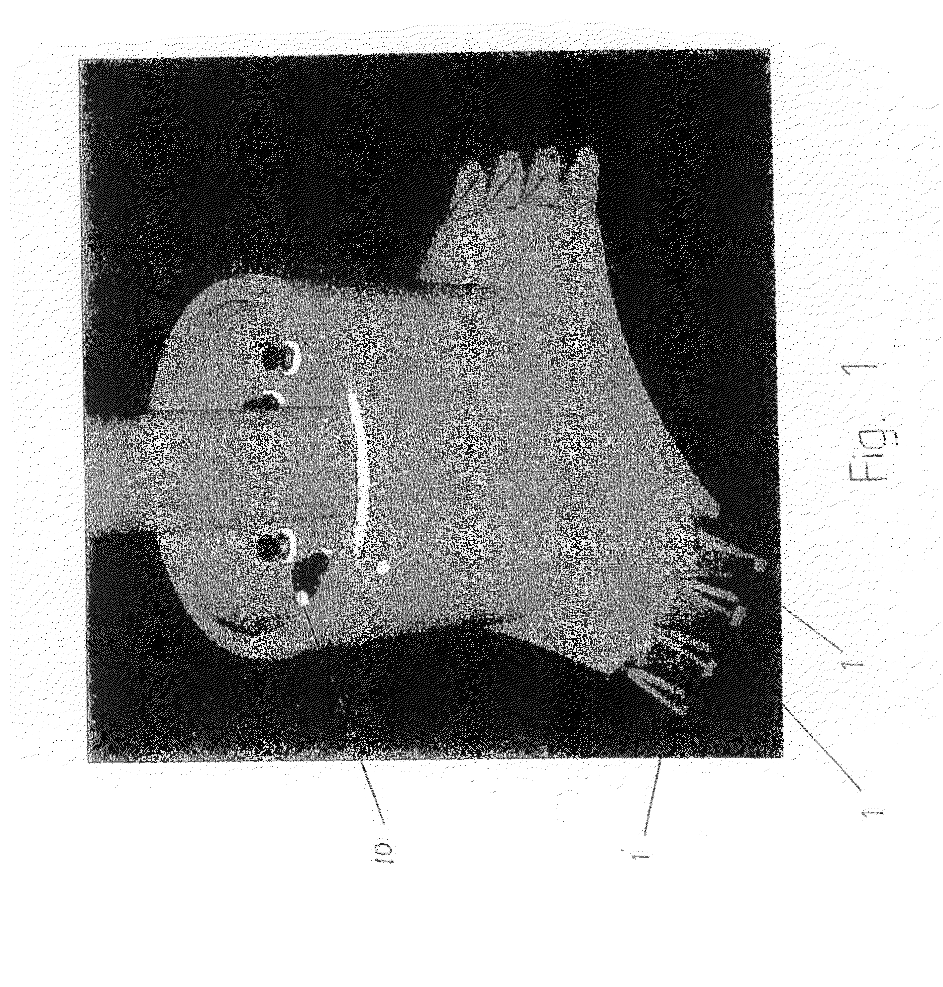
[0015]Reference is first made to FIG. 1 illustrating the inner geostationary part of a turret. The turret is mounted into or on a vessel, and the vessel can rotate around the inner geostationary part of the turret. In the lower part of the turret 9, cribs are arranged for hanging up of respective anchoring lines. Cross bars on the coupling part in the upper end of each anchoring line, fit into the respective cribs. Also, hanged-up risers 10 are illustrated.

[0016]It is no proviso for the invention that a turret or an FPSO-vessel or similar is used. The vessel can be any floating installation such as a rig, as the cribs can be mounted for example in the corners of the rig.

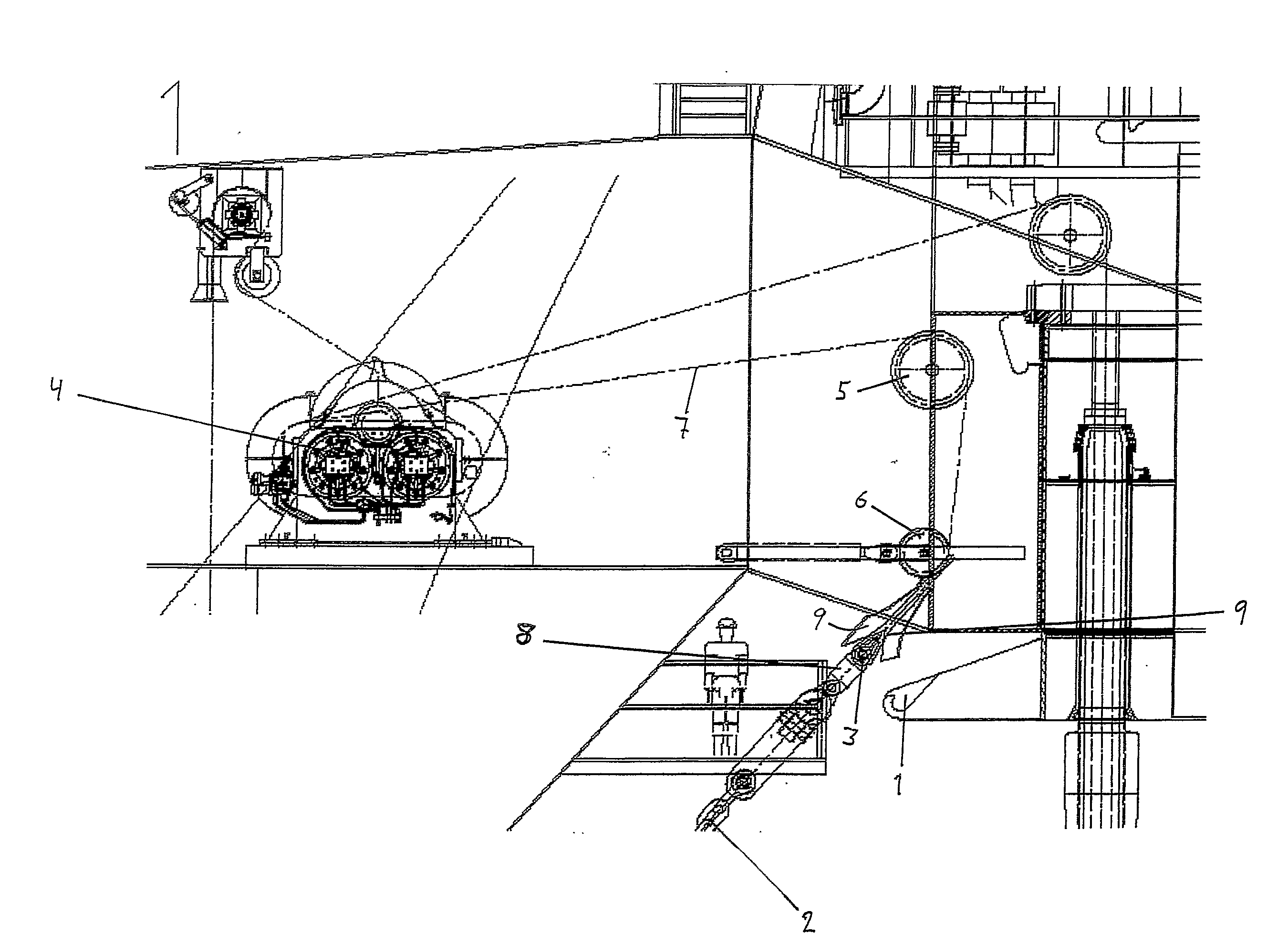
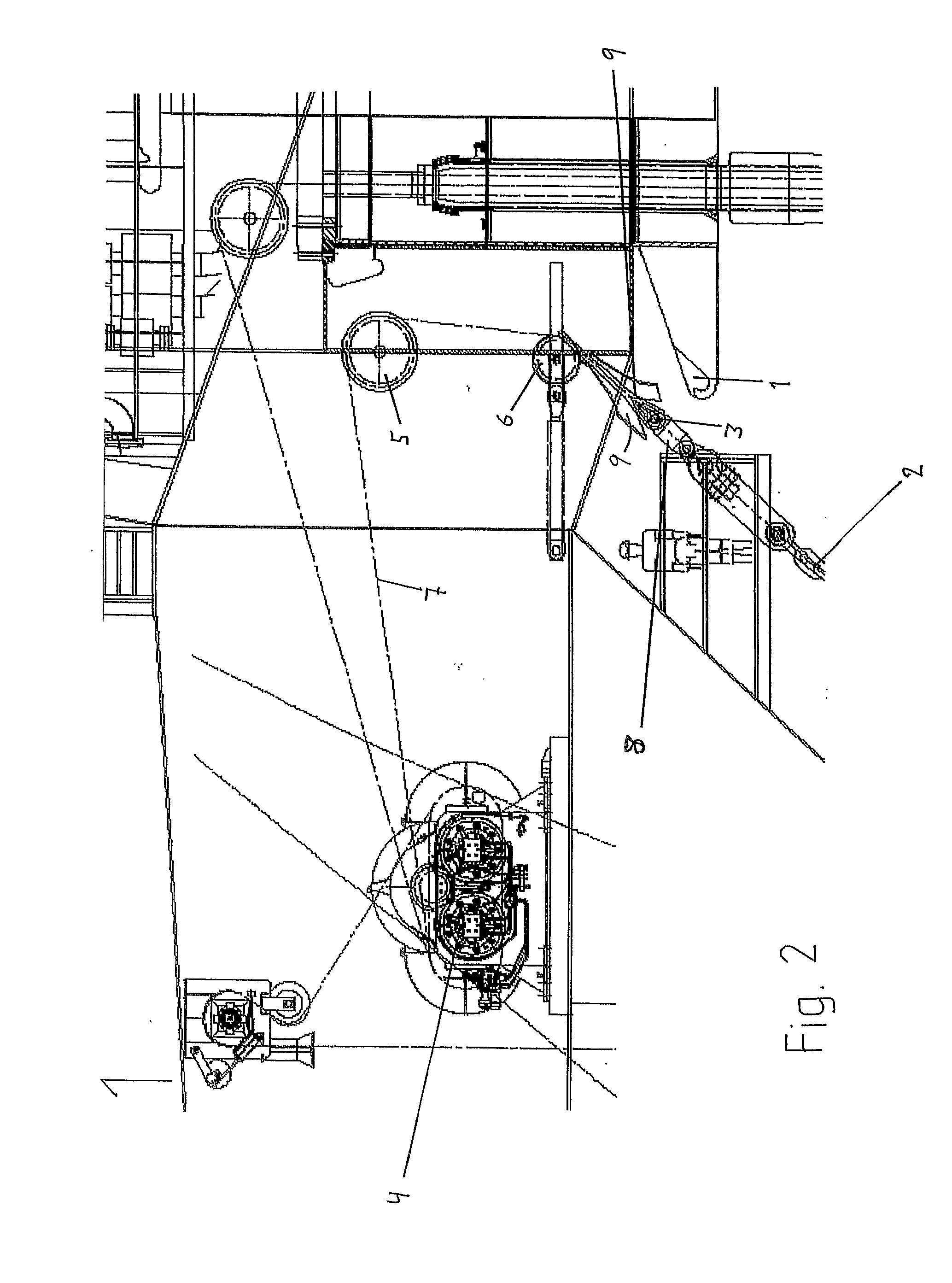
[0017]With reference to FIG. 2, it is illustrated how the pull-in of an anchoring line 2 is undertaken in order to place the coupling part 3 into the crib 1. More particularly, a winch 4 with guiding sheaves 5 and 6, over which guiding sheaves a pull-in wire 7 is arranged, is used. The anchoring line is pulled in unt...


PUM


Abstract

System for anchoring of a vessel, preferably at deep waters, comprising a number of anchoring lines, each anchoring line extending from a fastening means on the vessel to an anchor at the seabed, and the anchoring lines are preferably arranged tightly, obliquely down into the sea around the vessel in the form of spread anchoring, such that the vessel is maintained in a fixed, intended position.distinguished in that each anchoring line is fastened to an anchor and extends out in one length, without joinings, to an upper end where a coupling part is fastened, and the fastening means comprises a crib for each anchoring line, where each coupling part can be laid down in an intended, fastened position.Method for anchoring of a vessel, with use of the system according to the invention.

Description

FIELD OF THE INVENTION[0001]The present invention relates to anchoring of a vessel, preferably at deep waters, with spread anchoring preferably arranged tightly from the vessel. More particularly, the invention relates to a system and a method for anchoring of a vessel.BACKGROUND OF THE INVENTION AND PRIOR ART[0002]When a vessel, such as a FPSO—a vessel for floating production, storage and offloading—lies anchored, large forces are required to maintain the position of the vessel. The anchoring lines (the moorings) normally are spread out around a circumference of the vessel. Typically there are 50-100 tons tension in the anchoring lines for this purpose. Pull-in or connection of the anchoring lines is a comprehensive and expensive operation. Normally, the anchors are placed at the seabed in advance, with about half of the length of the anchoring line coupled to each specific anchor. On the vessel the upper half of the anchoring lines are connected, with a pin coupling through adapte...

Claims


Application Information

Patent Timeline
IPC IPC(8): B63B21/24B63BB63B21/22B63B21/50
CPCB63B21/50B63B21/22
Inventor ASKESTAD, SIGMUND
Owner ADVANCED PRODUCTION AND LOADING AS
Why Eureka
Try Eureka