Power transmission device for vehicle

a technology for transmission devices and vehicles, applied in mechanical devices, couplings, gears, etc., can solve problems such as torque fuse and irregular whirling of clutches

Active Publication Date: 2017-01-03
HONDA MOTOR CO LTD
View PDF17 Cites 3 Cited by
  • Summary
  • Abstract
  • Description
  • Claims
  • Application Information

AI Technical Summary

Benefits of technology

[0007]It is therefore an object to provide an improved power transmission device for a vehicle which, with a torque fuse provided in a

Problems solved by technology

With the conventionally-known technique, however, the torque fuse is provided in a desired portion without appropriate consideration being made about the position where the torque fuse should be provided.
But, if the conventional to

Method used


Image

  • Power transmission device for vehicle
  • Power transmission device for vehicle
  • Power transmission device for vehicle

Examples


Embodiment Construction

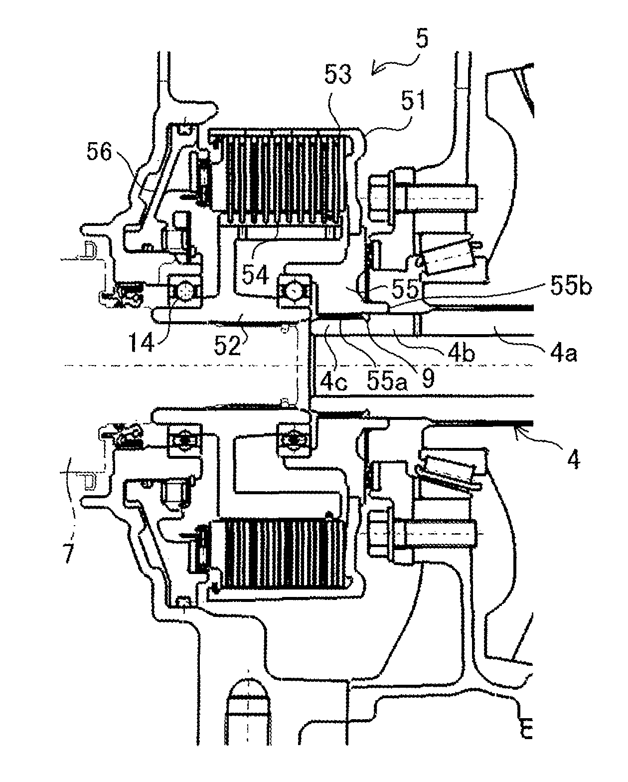
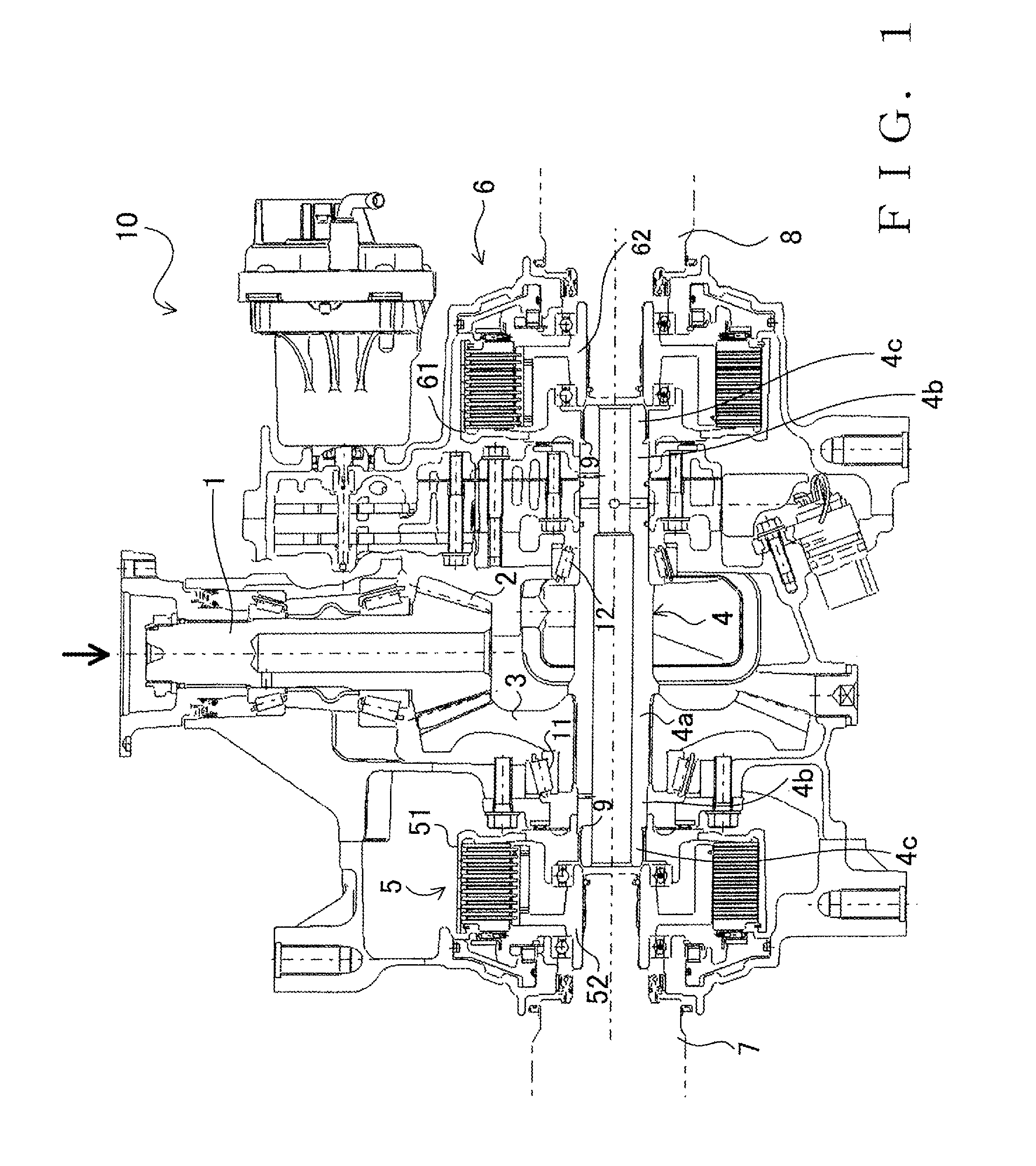
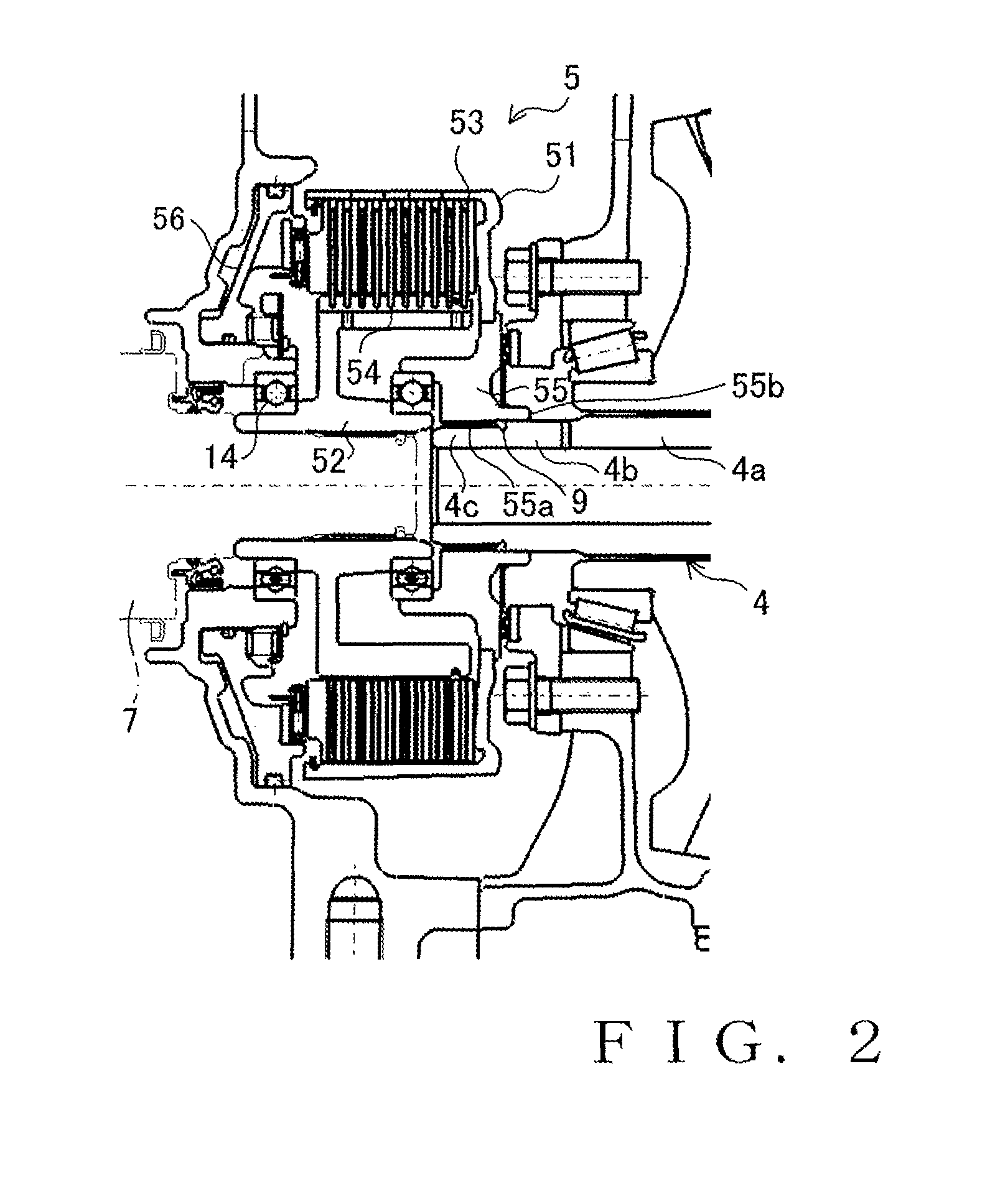
[0013]An embodiment of a power transmission device for a vehicle (vehicular power transmission device) of the present invention shown in FIG. 1 is constructed as a differential mechanism 10 for distributing rotation of a drive shaft 1 to left and right wheels (not shown). The drive shaft 1 is connected to a not-shown propeller shaft so that rotary motion is transmitted from a not-shown drive source (engine) to the drive shaft 1. The differential mechanism 10 includes: a driving bevel gear 2 rotatable integrally with the drive shaft 1; a driven bevel gear 3 meshing with the driving bevel gear 2; a center shaft 4 disposed to extend in a direction intersecting the drive shaft 1 and connected to the driven bevel gear 3 for integral rotation with the driven bevel gear 3; clutch units 5 and 6 disposed to the left and right of the center shaft 4; and left and right output shafts 7 and 8 for transmitting respective outputs of the clutch units 5 and 6 to the left and right wheels (not shown)...


PUM


Abstract

In a power transmission device for a vehicle, a boss portion of a clutch guide, which is an input-side rotation member of a clutch unit, includes: a spline portion spline-connected to a small-diameter portion at one end of a center shaft which is an input shaft; and a fitting portion that extends further from the spline portion in an axial direction to contact the outer circumference of a medium-diameter portion of the center shaft. A recess functioning as a torque fuse is formed in the medium-diameter portion of the center shaft corresponding to the fitting portion. When the center shaft is severed or disconnected at the recess, the medium-diameter portion of the severed cut center shaft can still remain within the fitting portion, so that appropriate centering can be secured and stable self-propulsion of the vehicle can be secured without unwanted misalignment of the axis of rotation of the clutch.

Description

TECHNICAL FIELD[0001]The present invention relates generally to power transmission devices for vehicles and more particularly to a torque fuse (most torsionally-frangible portion or fracturing portion for emergency) in a power transmission shaft of a four-wheel drive vehicle.BACKGROUND ART[0002]Patent Literatures 1, 2 and 3 identified below disclose torque-distribution type power transmission devices in four-wheel drive vehicles. More specifically, Patent Literature 1 discloses that a clutch for connecting and disconnecting drive power transmission is provided between a center drive shaft for transmitting rotary motion of a drive source (engine) to rear wheels and a differential unit for the rear wheels, and that switching is made between two-wheel drive and four-wheel drive through connection and disconnection, by the clutch, of the drive power transmission. Further, Patent Literatures 2 and 3 disclose that clutches are provided in corresponding relation to left and right wheels in...

Claims


Application Information

Patent Timeline
IPC IPC(8): F16H37/08F16H48/19F16D9/06F16H48/22F16H35/10F16D25/0638F16H48/14F16H48/34
CPCF16H48/19F16D9/06F16H35/10F16H48/22F16D25/0638F16H48/145F16H48/147F16H2035/103F16H2048/343
Inventor IMAMORI, SATOSHITSUCHIHASHI, MAKOTO
Owner HONDA MOTOR CO LTD
Why Eureka
Try Eureka