Pendulum absorber with sliding joint

a technology of sliding joint and absorber, which is applied in the direction of shock absorbers, springs/dampers, rotating vibration suppression, etc., can solve the problems of limited longevity of the spacing element in the absorber, torsional vibration generation, etc., and achieve the effect of reducing noise, vibration, vibration and harshness in the engine, and reducing vibration

Inactive Publication Date: 2017-01-17
FORD GLOBAL TECH LLC
View PDF10 Cites 1 Cited by
  • Summary
  • Abstract
  • Description
  • Claims
  • Application Information

AI Technical Summary

Benefits of technology

[0002]Centrifugal pendulum absorbers are used in machines to reduce vibrations (e.g., torsional vibrations) of rotating components. In engines crankshafts, flywheels, etc., may generate torsional vibration. Centrifugal pendulum absorbers may be placed in engines to attenuate the torsional vibration. As a result, noise, vibration, and harshness (NVH) is decreased in the engine. Specifically, pendulum absorbers may be coupled to a crankshaft or a flywheel to dampen torsional vibrations, thereby increasing component longevity and decreasing engine noises.
[0004]As such in one approach, a pendulum absorber assembly is provided. The pendulum absorber assembly includes a rotor coupled to a rotating shaft, a pendulum absorber moveably coupled to the rotor and including a preloaded sliding joint coupled to a first counterbalancing section and a second counterbalancing section, the preloaded sliding joint configured to urge the first counterbalancing section away from the second counterbalancing section, and two pins, each of the pins coupled to a different counterbalancing section and the rotor. In one example, each counterbalancing section includes a counterbalance pin opening mated with a corresponding pin. The preloaded sliding joint enables a constant force to be exerted on the pin openings by the pins during low speed operation of the crankshaft to reduce vibration caused by play between the pins and pin openings. In other words, the float of the pin in the pin opening is substantially inhibited at low engine speeds. As a result, NVH generated by the drive-train is reduced, thereby increasing customer satisfaction and increasing transmission longevity.

Problems solved by technology

In engines crankshafts, flywheels, etc., may generate torsional vibration.
For instance, the longevity of the spacing element in the absorber may be limited.

Method used


Image

  • Pendulum absorber with sliding joint
  • Pendulum absorber with sliding joint
  • Pendulum absorber with sliding joint

Examples


Embodiment Construction

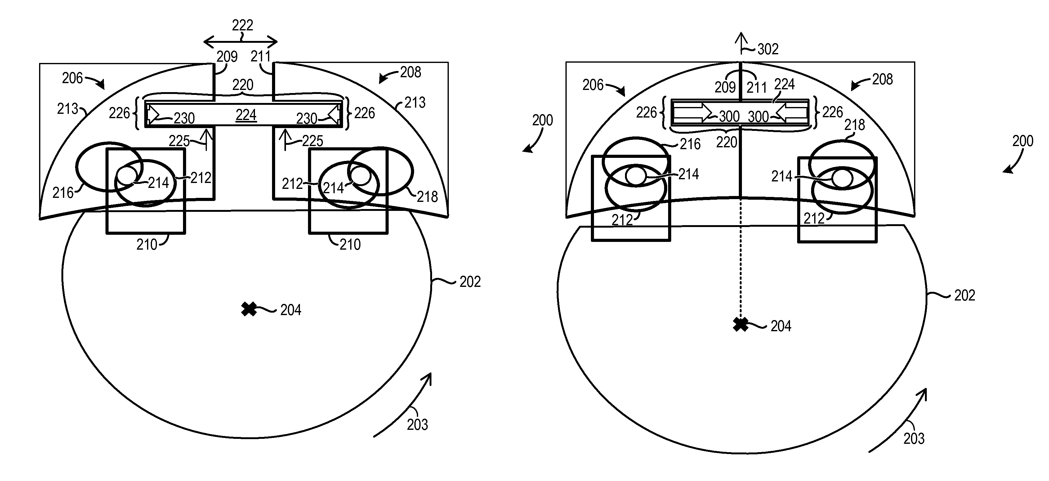
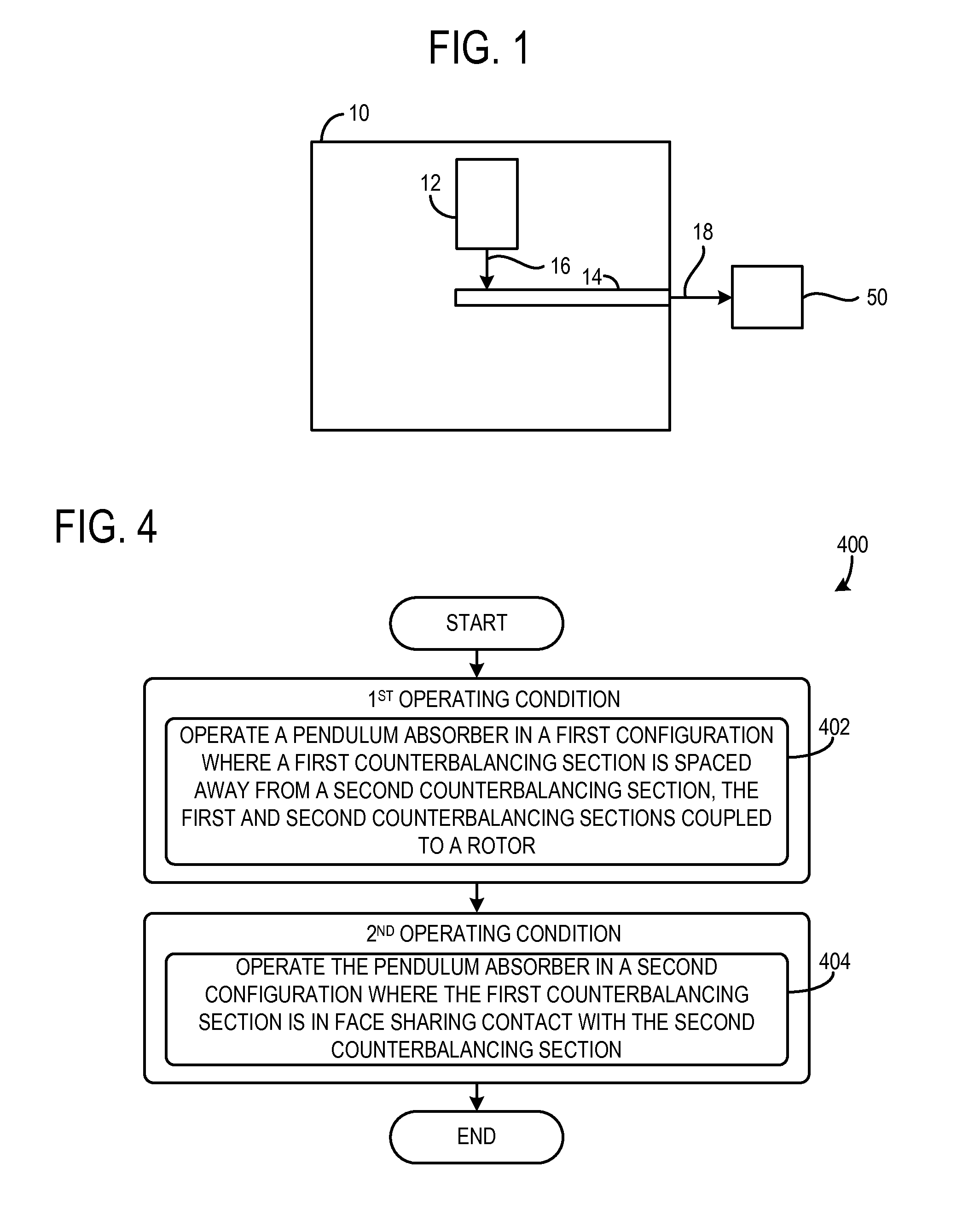
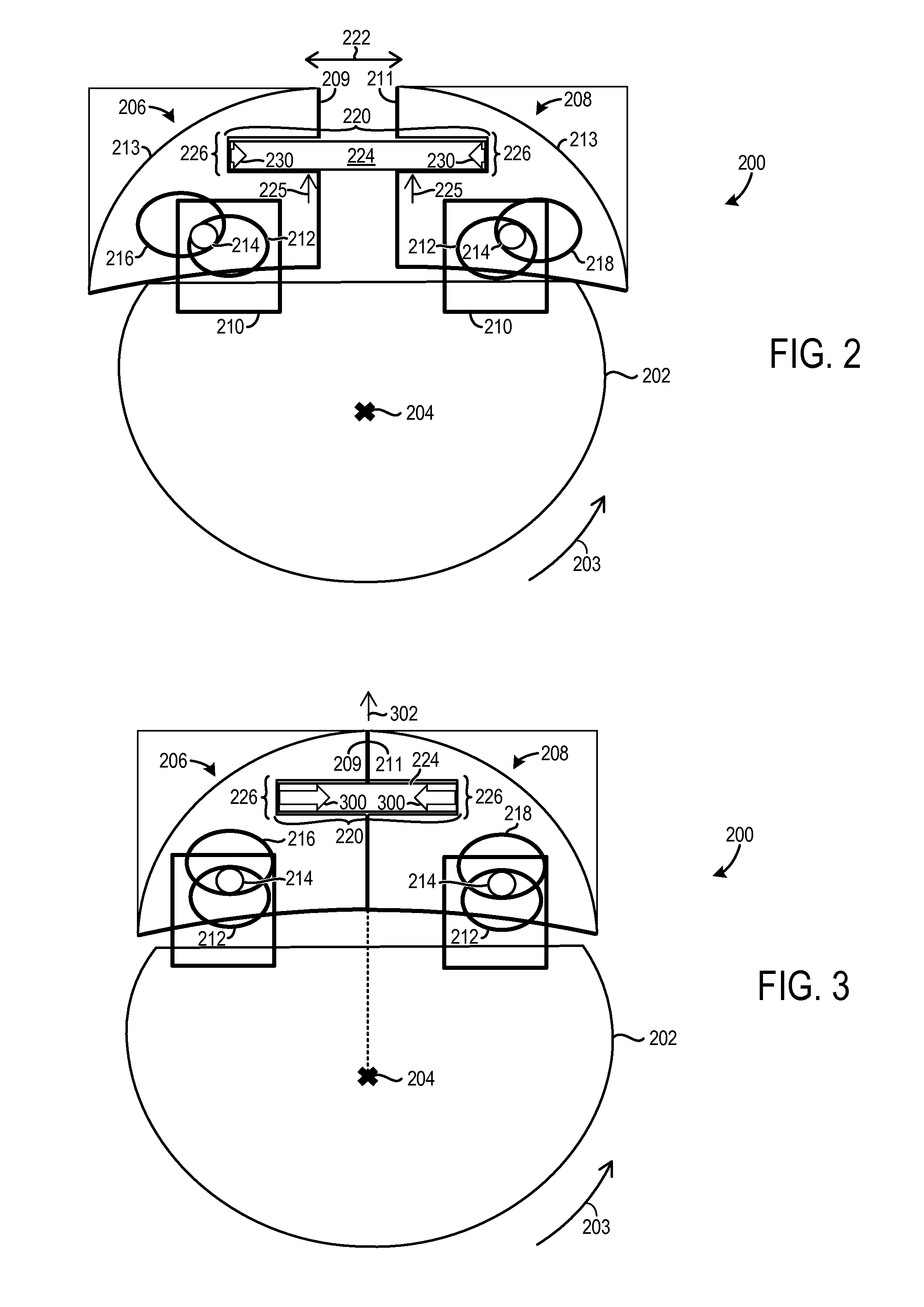
[0011]A pendulum absorber having a preloaded sliding joint configured to urge two counterbalancing masses away from one another is described herein. This functionality of the sliding joint enables the counterbalancing masses to be spaced away from one another during low speed operation to maintain contact between pins and pin openings in the pendulum absorber. Consequently, noise and vibration caused by play between the pins and the pin openings in the pendulum absorber is reduced (e.g., substantially inhibited), during low speed operation, for example. As a result, noise, vibration, and harshness (NVH) generated by the pendulum absorber is reduced, thereby increasing component longevity. It will be appreciated that the counterbalancing masses may be urged away from one another in a direction perpendicular to a direction of the movement of the counterbalancing masses cause by centrifugal forces, in one example. In this way, movement of the counterbalancing masses away from one anoth...


PUM


Abstract

A pendulum absorber assembly including a rotor coupled to a rotating shaft, a pendulum absorber moveably coupled to the rotor and including a preloaded sliding joint coupled to a first counterbalancing section and a second counterbalancing section, the preloaded sliding joint configured to urge the first counterbalancing section away from the second counterbalancing section, and two pins, each of the pins coupled to a different counterbalancing section and the rotor.

Description

FIELD[0001]The present disclosure relates to a pendulum absorber with a sliding joint and a method for operation of the pendulum absorber.BACKGROUND AND SUMMARY[0002]Centrifugal pendulum absorbers are used in machines to reduce vibrations (e.g., torsional vibrations) of rotating components. In engines crankshafts, flywheels, etc., may generate torsional vibration. Centrifugal pendulum absorbers may be placed in engines to attenuate the torsional vibration. As a result, noise, vibration, and harshness (NVH) is decreased in the engine. Specifically, pendulum absorbers may be coupled to a crankshaft or a flywheel to dampen torsional vibrations, thereby increasing component longevity and decreasing engine noises.[0003]US 2013 / 0233125 discloses a centrifugal pendulum absorber in an engine. The centrifugal pendulum absorber includes a preloaded spacing element placed between separate pendulum absorber elements to restrict movement (e.g., lock-up) of the pendulum absorber elements, thereby...

Claims


Application Information

Patent Timeline
Patent Type & Authority Patents(United States)
IPC IPC(8): F16F7/10F16F15/14F16F7/116
CPCF16F7/10F16F7/116F16F15/145
Inventor JAIN, ABHISEK
Owner FORD GLOBAL TECH LLC
Why Eureka
Try Eureka