Universal loading station for laser 3D printer

Active Publication Date: 2017-01-24
JIANGSU RICH OPTO TECH CO LTD
View PDF13 Cites 0 Cited by
  • Summary
  • Abstract
  • Description
  • Claims
  • Application Information

AI Technical Summary

Benefits of technology

[0005]Technical problem to be solved by the present invention is to provide a simple and e

Problems solved by technology

In this 3D printer, a lifting station above a vertical slot can only move up and down, and the angle of the lifting station cannot be adjusted automatically based on the changes of the angle of the resin surface in a resin tank.
Thus, when the resin surface angle in the resin tank is an inclined angle, the lifting station a

Method used


Image

  • Universal loading station for laser 3D printer
  • Universal loading station for laser 3D printer
  • Universal loading station for laser 3D printer

Examples


Example

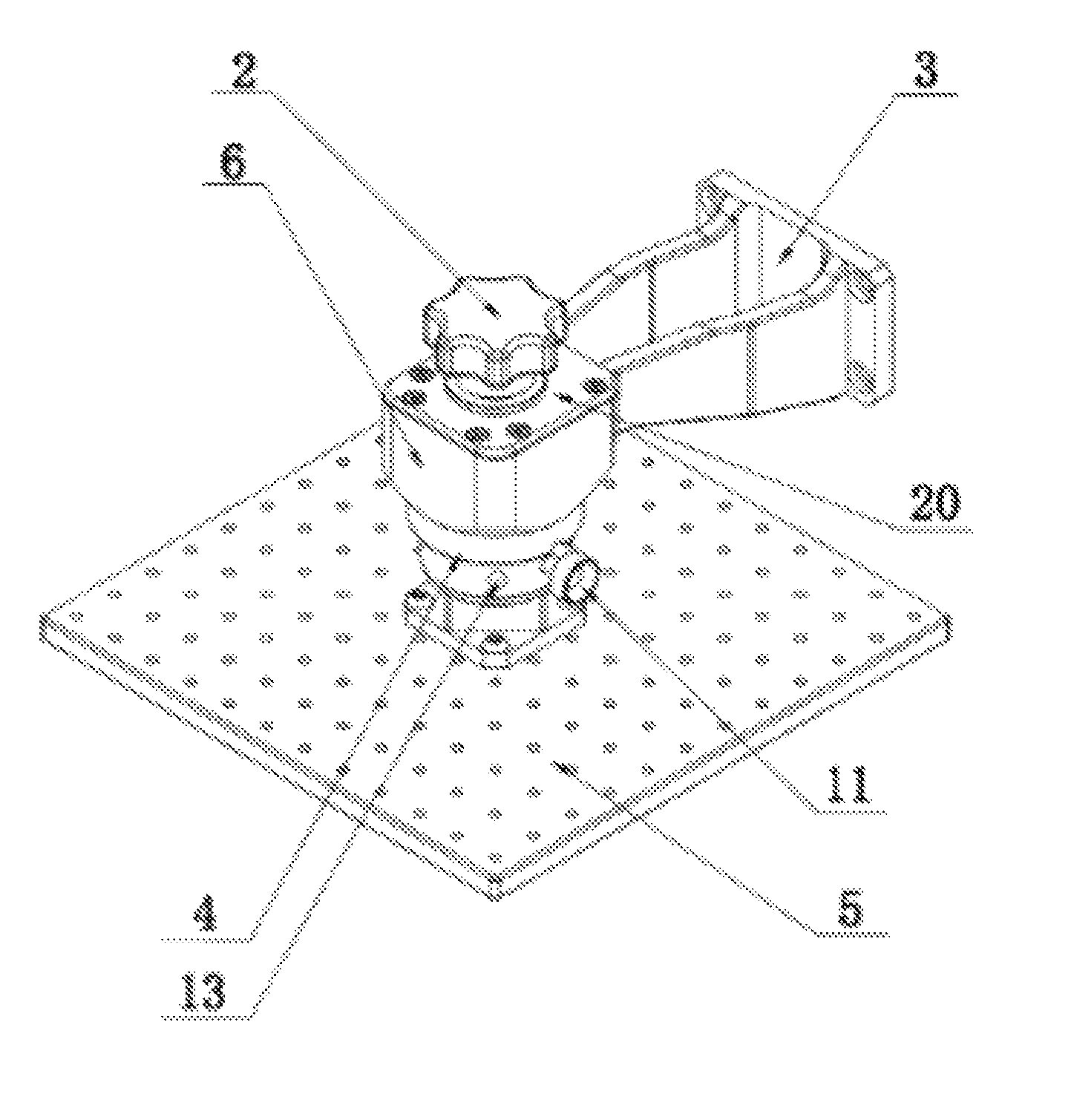
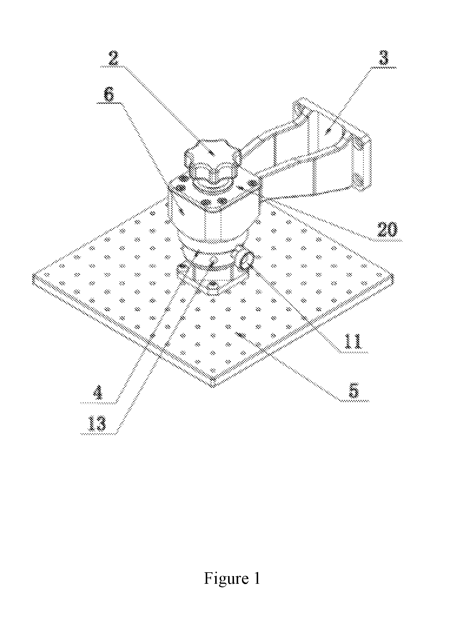
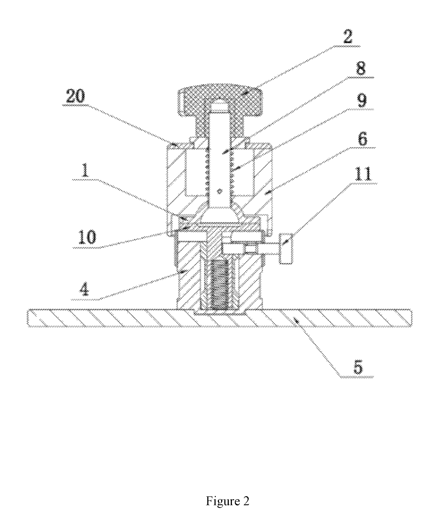
[0016]As shown in FIGS. 1, 2 and 3, a laser 3D printer with a universal loading station includes a knob 2, a ball screw 8, a telescopic connecting ring 1, a telescopic connecting rod 10, a protective cover 4 and a loading plate 5. The top of the ball screw ball screw 8 and the bottom of the knob 2 are connected by a threaded connection. The ball screw 8 is below the knob 2 and has an outer sleeve which includes a spring 9. A fixed connection sleeve 6 surrounds the outer sleeve of the spring 9. A top plate 20 is provided on the top of the fixed connection sleeve 6. The top of the fixed connection sleeve 6 and the top plate 20 are connected by screws at the edge of the top plate 20. The top plate 20 includes a ninth hole in the center. The top plate is placed onto the ball screw 8 through the ninth hole. A connecting arm 3 is connected to a side of the fixed connection sleeve 6. The universal loading station is connected to a lifting mechanism of the 3D printer via the connecting arm ...


PUM


Abstract

A universal loading station for a 3D printer includes a knob, a ball screw, a telescopic connecting ring, a telescopic connecting rod, and a loading plate. The top of the ball screw ball screw and the bottom of the knob are connected by a threaded connection. The ball screw is below the knob and includes an outer sleeve which includes a spring. A fixed connection sleeve surrounds the outer sleeve of the spring. A connecting arm is connected to a side of the fixed connection sleeve. The bottom of the ball screw is connected to the telescopic connecting ring. The bottom of the telescopic connecting ring includes a first hemispherical recess, and the center of the first hemispherical recess includes a first hole. The telescopic connecting ring is placed onto the ball screw through the first hole.

Description

[0001]The present application claims the benefit of Chinese Application No. 201610319949.7, filed on May 13, 2016, which is incorporated by reference for all purposes as if fully set forth herein.TECHNICAL FIELD[0002]The present invention relates to the field of three dimensional (3D) printing, particularly to a universal loading station for a laser 3D printer.BACKGROUND[0003]3D printing is a technology based on mathematical model files, using adhesive materials, such as special wax, powdered metal or plastic materials, applying a layer-by-layer printing method to construct an object. It is different from a traditional material construction method, and is a new three dimensional layer-by-layer printing method via gradually adding materials. With the rapid development of 3D printing technology, laser technology, due to its speed and accuracy, has been widely applied to 3D printing as the source of energy. Specifically, photosensitive resin stereolithography apparatus (SLA) has domina...

Claims


Application Information

Patent Timeline
IPC IPC(8): B25J17/02B29C67/00B33Y30/00
CPCB29C67/0092B25J17/0208B25J17/0233B33Y30/00B29C64/227
Inventor WU, YIN
Owner JIANGSU RICH OPTO TECH CO LTD
Why Eureka
Try Eureka