
Disposable laryngoscope blade

Pending Publication Date: 2022-01-06
PAVISUS AS
View PDF0 Cites 0 Cited by
  • Summary
  • Abstract
  • Description
  • Claims
  • Application Information

AI Technical Summary

Benefits of technology

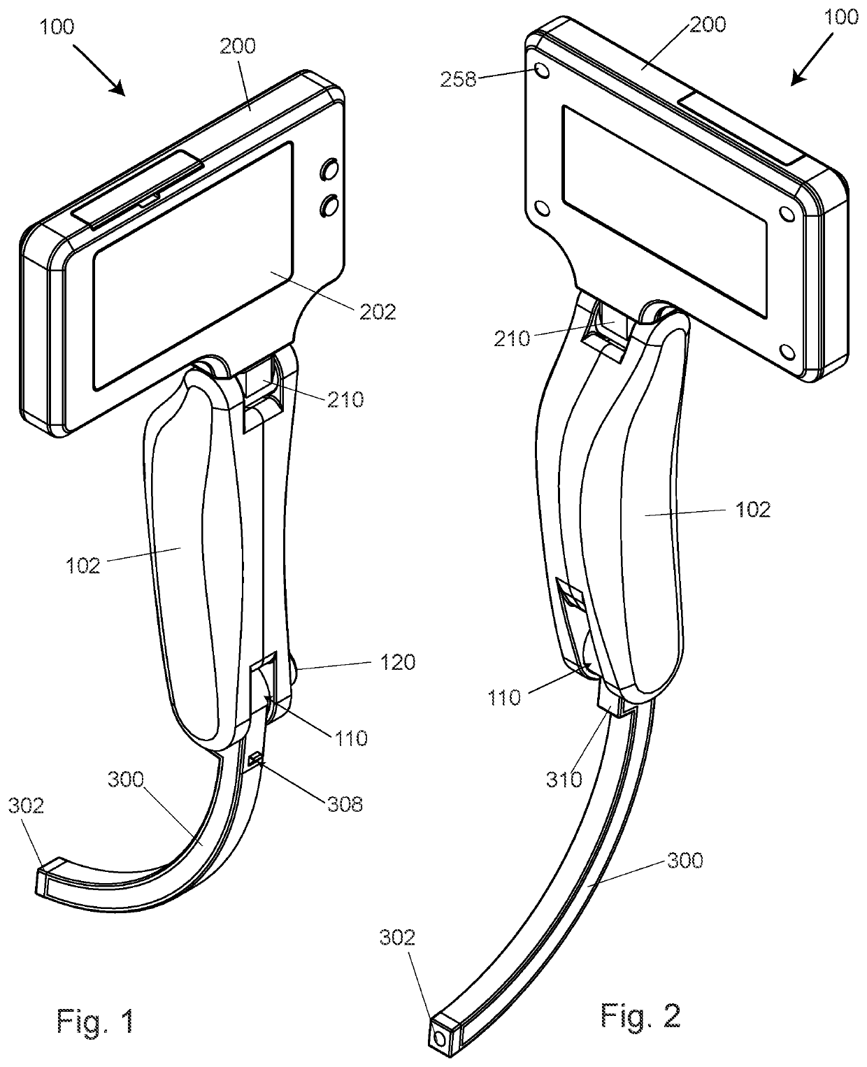
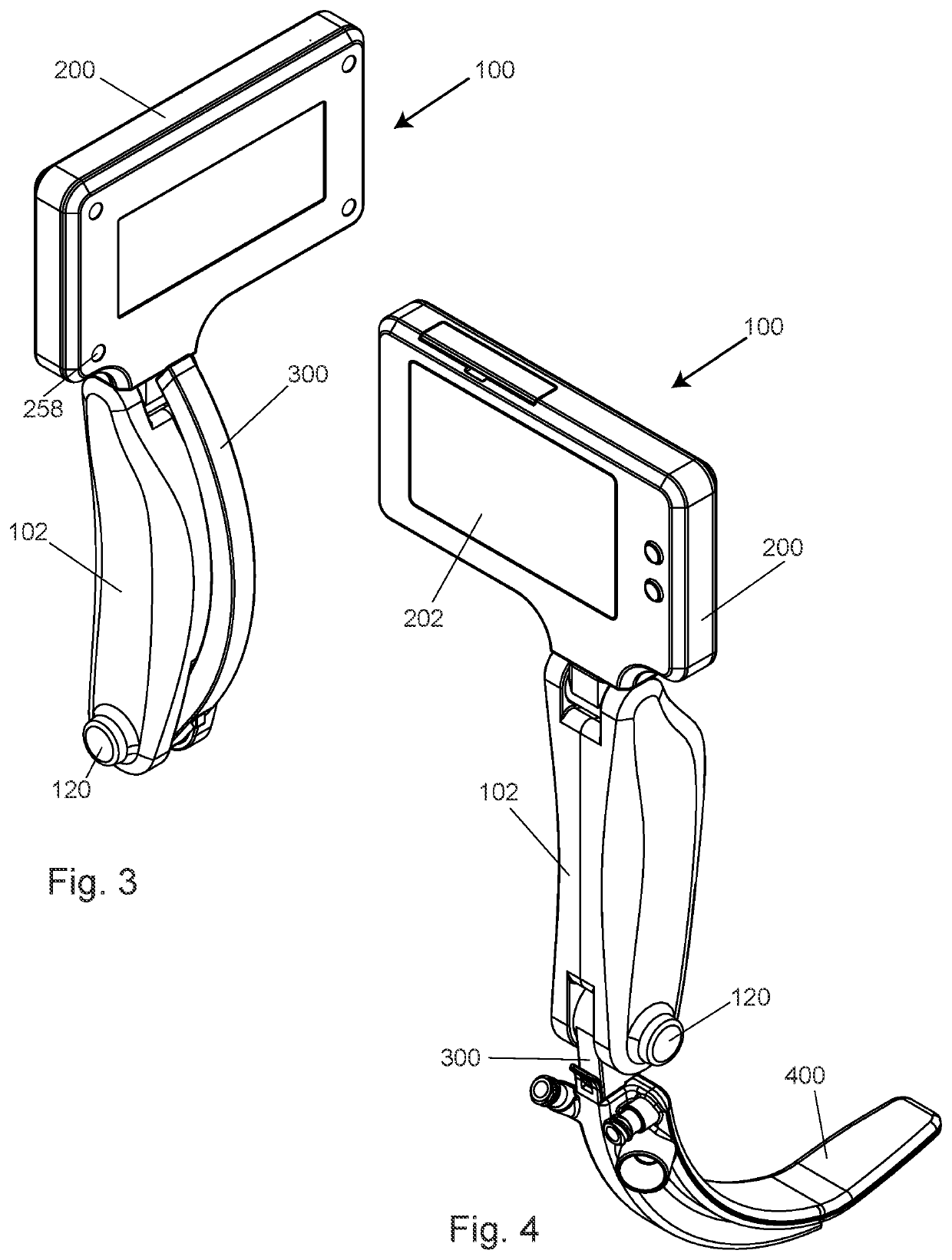
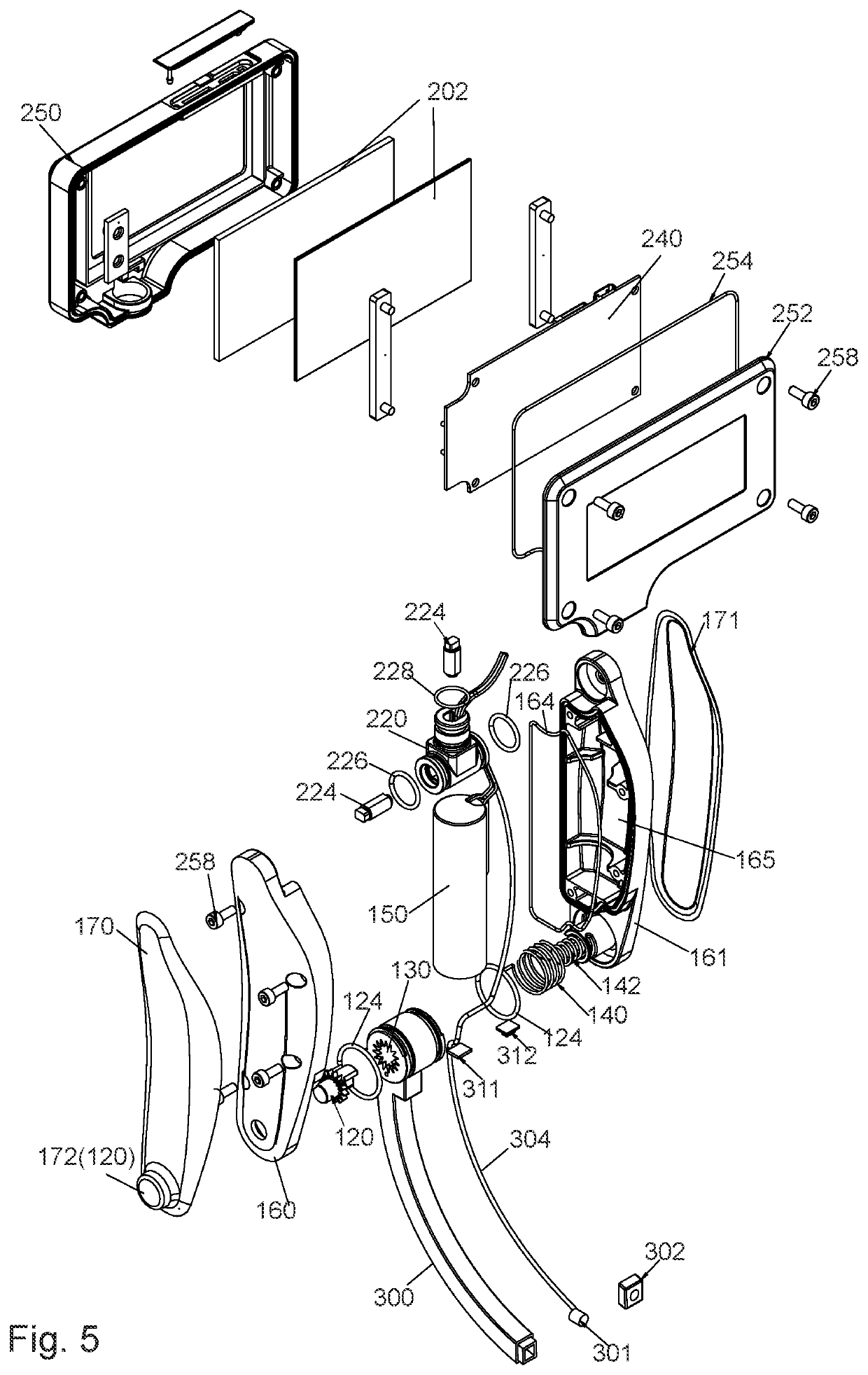
This patent describes an improved laryngoscope device that is easy to use and clean. The device features a disposable video laryngoscope blade that can be easily detached from the laryngoscope and replaced. The blade has channels for transporting fluids and a suction outlet connector for collecting bodily fluids from the patient. This makes the device hygienic and helps medical personnel perform critical life-aid procedures with ease. The device also includes a linkage device for positioning the communication unit at different angles relative to the laryngoscope body, an apparatus body, and a suction outlet connector for bodily fluids.

Problems solved by technology

This current configuration of the video laryngoscope may make it difficult for an individual to insert the video laryngoscope into the oral cavity of a patient when the patient's head is in an inconvenient posture or position.
In some cases, the laryngoscope's configuration might not be optimal for operation, and a display unit that is attached to the laryngoscope's handle may subsequently end up at a location that renders visual observation thereof by the individual performing the intubation cumbersome.
Furthermore, video laryngoscopes may necessitate more stringent cleaning procedures compared to traditional laryngoscopes, due to their more complex shape, structure and functionality.

Method used


Image

  • Disposable laryngoscope blade
  • Disposable laryngoscope blade
  • Disposable laryngoscope blade

Examples


Embodiment Construction

[0047]Although specific configurations and arrangements are discussed, it should be understood that this is done for illustrative purposes only. A person skilled in the pertinent art will recognize that other configurations and arrangements can be used without departing from the spirit and scope of the present disclosure. It will be apparent to a person skilled in the pertinent art that this disclosure can also be employed in a variety of other applications.

[0048]It is noted that references in the specification to “one embodiment,”“an embodiment,”“an example embodiment,” etc., indicate that the embodiment described may include a particular feature, structure, or characteristic, but every embodiment may not necessarily include the particular feature, structure, or characteristic. Moreover, such phrases do not necessarily refer to the same embodiment. Further, when a particular feature, structure or characteristic is described in connection with an embodiment, it would be within the k...


PUM


Abstract

Described herein is a video laryngoscope designed for easy and safe operation comprising an apparatus body, a laryngoscope camera arm unit, and an associated laryngoscope blade releasably attached to the laryngoscope camera arm unit. The laryngoscope camera arm unit is angularly adjustable by use of a rotary linkage member connected to a distal end of the apparatus body. A communication unit is connected to a linkage device at a proximal end of the apparatus body. A light source and a video camera are located on the laryngoscope camera arm unit. The laryngoscope blade has at least two internal fluidic channels for delivering fluid to oral cavity regions of a patient and providing suction of bodily fluids from the patient.

Description

CROSS-REFERENCE TO RELATED APPLICATIONS[0001]This application claims priority to Norwegian App. No. 20200790 filed on Jul. 6, 2020 and Norwegian App. No. 20200789 filed on Jul. 6, 2020, the disclosures of which are incorporated by reference herein in their entireties. This application is related to co-pending U.S. patent application Ser. No. ______ (Atty. Dkt. No. 4750.0020001) by Daniel Stoffel, entitled “Video Laryngoscope Apparatus,” filed on even date herewith, the disclosure of which is incorporated by reference herein in its entirety.BACKGROUNDField[0002]Embodiments of the application relate to a medical instrument and more particularly an instrument for performing a medical procedure in the field of anaesthesiology where a breathing tube is placed into the patient's trachea or for performing medical visual examinations of the respiratory tract.Background[0003]Video laryngoscopes are used to assist personnel performing tracheal intubations in patients. A video laryngoscope app...

Claims


Application Information

Patent Timeline
IPC IPC(8): A61B1/267A61B1/00A61B1/015A61B1/06A61M16/01A61B1/05
CPCA61B1/267A61B1/00101A61B1/015A61B1/05A61B1/00103A61M16/01A61B1/0684A61B1/00105A61B1/126A61M16/0488A61M2205/505A61M19/00A61M2202/0208A61M2202/0241A61M16/208A61M2205/332A61M2205/587A61M16/0463A61M2205/80A61M2205/8206A61M2205/581A61M2205/583A61M2205/582A61M2205/52G16H20/40A61M2205/3584A61M2205/8243A61M2205/3553A61M2205/3592A61M16/024A61M2205/507A61B1/0623A61B1/00034A61B1/0052A61B1/008A61B1/00128A61B1/00055A61M2202/0007A61B1/0005A61B1/0676A61B1/00016
Inventor STOFFEL, DANIEL
Owner PAVISUS AS
Learn More