Electronic interface

Active Publication Date: 2017-01-24
TYCO ELECTRONICS AMP GMBH
View PDF20 Cites 3 Cited by
  • Summary
  • Abstract
  • Description
  • Claims
  • Application Information

AI Technical Summary

Benefits of technology

[0007]An object of the invention is to provide an improved electronic interface and, in particular an improved USB interface. Accordingly, an electronic interface according to the invention is provided and includes a shield having a first shield element, a second shield element, and a c

Problems solved by technology

In both known designs, a significant empty space, generally a slot, of approximately 270° in a peripheral direction exists between the base region and the inte

Method used


Image

  • Electronic interface
  • Electronic interface
  • Electronic interface

Examples


Embodiment Construction

)

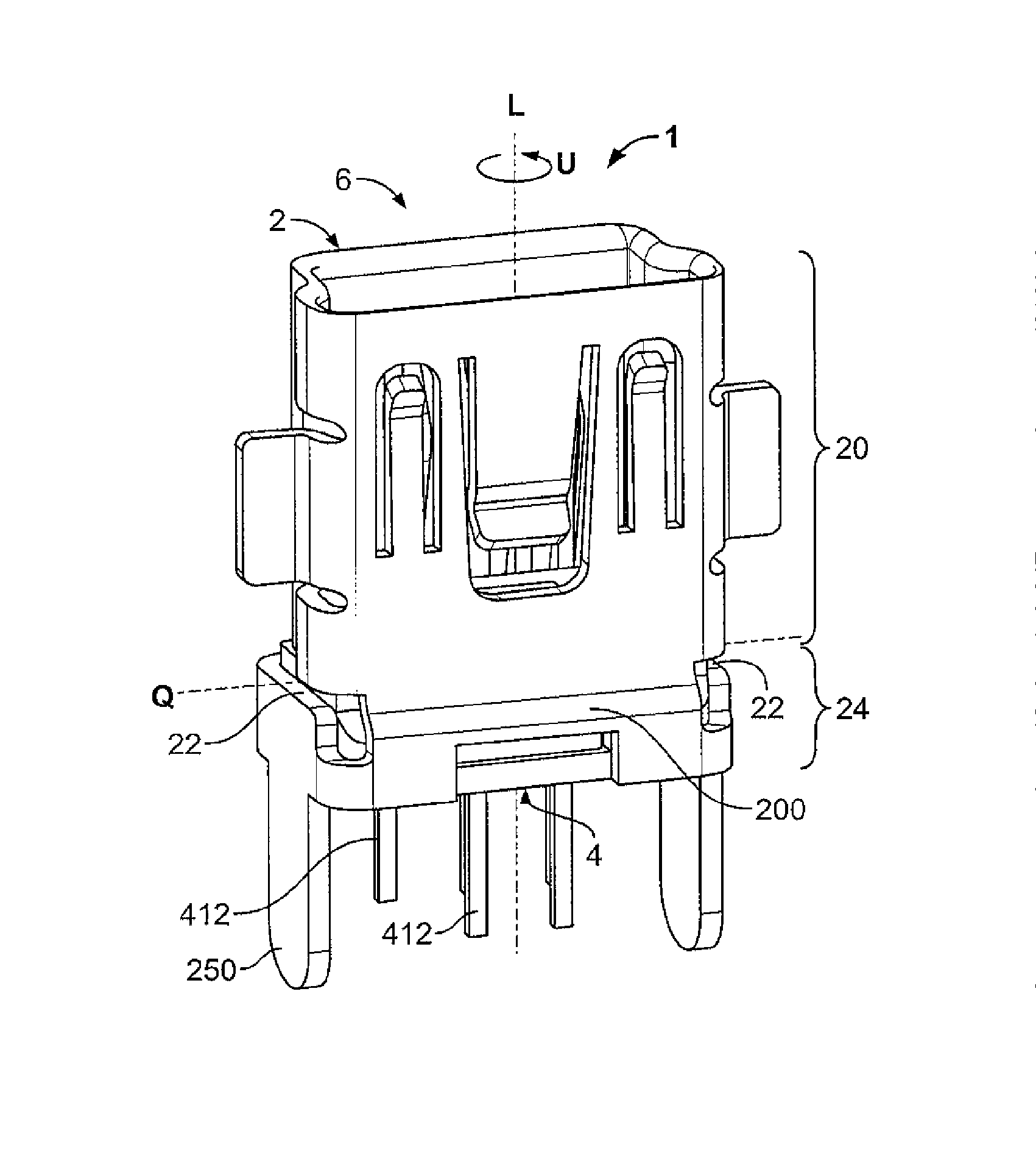
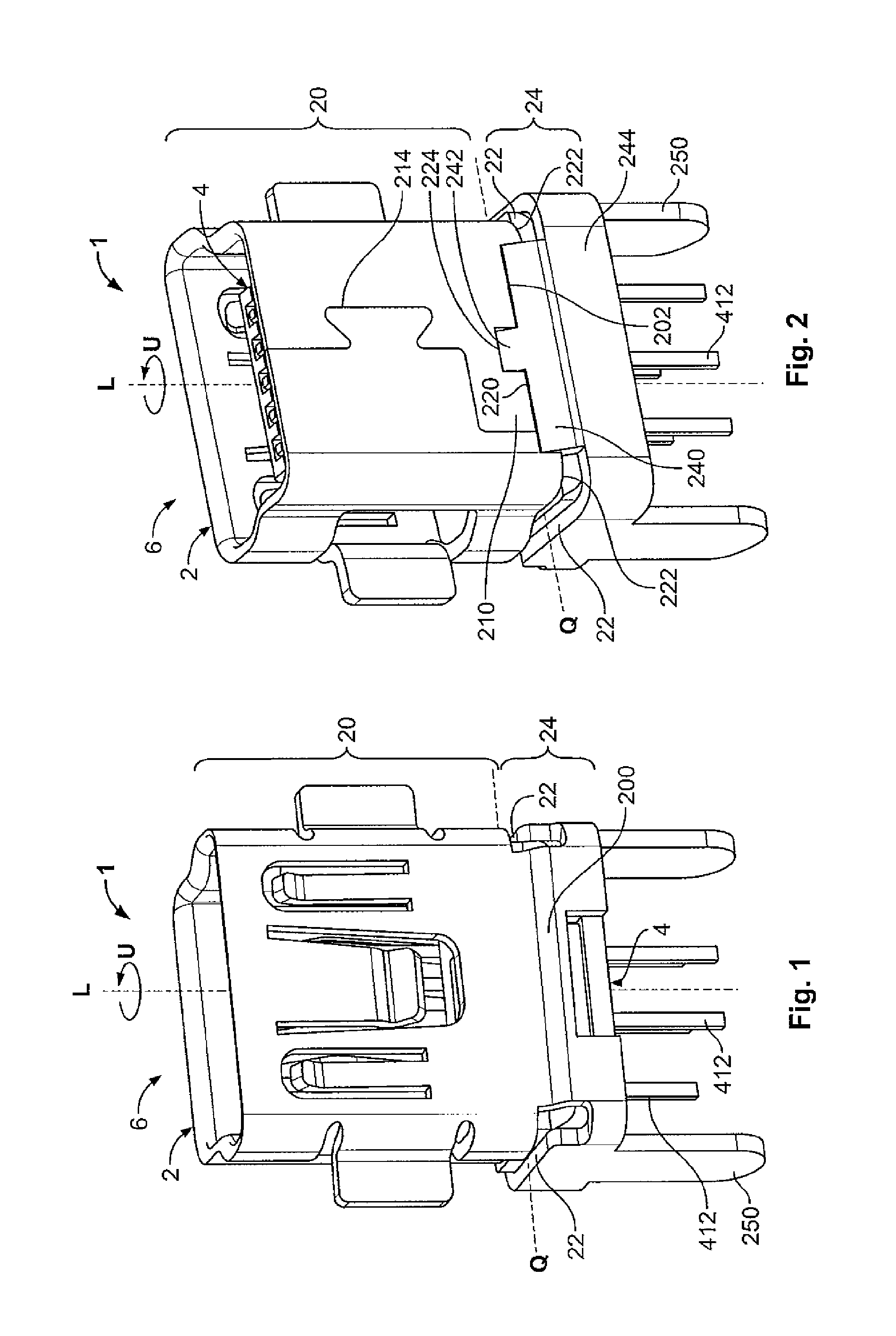
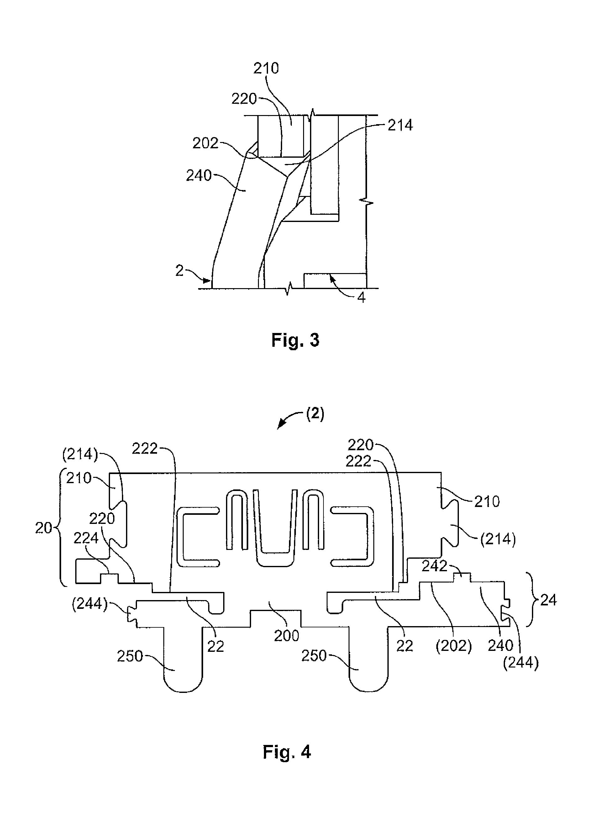
[0017]Now with reference to the drawings, an embodiment of an electronic interface 1 according to the invention will be discussed.

[0018]As shown in FIGS. 1, 2, 8, the electronic interface 1 is in the form of a USB interface and, in particular, a mini-USB or micro-USB interface. However, the invention is not limited to the embodiment illustrated but may in principle be applied to all electronic interfaces. Thus, for example, it is possible to apply the invention to any connection devices. Thus, for example, the invention may be used in a plug type device, a socket connector, a plug type connector, a (printed circuit board) pin contact strip, a (PCB) header, and etcetera.

[0019]The electronic interface 1 generally includes a shield 2 and a contact assembly 4. The contact assembly 4 is mounted inside the shield 2, with the contact assembly 4 being retained by an engagement member inside the shield 2. The front region of the electronic interface 1, from which a mating connector (not ill...


PUM


Abstract

An electronic interface is provided and includes a shield having a first shield element, a second shield element, and a connection section. The second shield element is spaced apart from the first shield element along a length of the shield and has a width different than a width of the first shield element. The connection section electrically connects the first shield element and the second shield element.

Description

CROSS-REFERENCE TO RELATED APPLICATIONS[0001]This application is a continuation of PCT International Application No. PCT / IB2013 / 056634 filed Aug. 13, 2013, which claims priority under 35 U.S.C. §119 to German Application 102012215377.2, filed Aug. 30, 2012.FIELD OF THE INVENTION[0002]The invention relates to an electronic interface and, in particular, to a USB interface.BACKGROUND[0003]A large number of electronic connectors are known in electrical engineering and electronics that are used to transmit electrical signals or voltages and optionally electrical currents with the largest possible range of voltages, data rates or frequencies and optionally electrical currents. In particular, in the automotive sector, electronic interfaces for such connections must permanently ensure correct transmission of electronic signals or data and optionally electrical power with significant temperature loading in a passenger compartment with a large number of insertion cycles.[0004]Such known elect...

Claims


Application Information

Patent Timeline
IPC IPC(8): H01R13/6582H01R13/516H01R13/6581H01R12/71
CPCH01R13/6582H01R13/516H01R13/6581H01R12/716
Inventor REINHARDT, MARCFLITTNER, FRANK
Owner TYCO ELECTRONICS AMP GMBH
Why Eureka
Try Eureka