
System and method for variation of the opening speed of a fuel tank valve

Inactive Publication Date: 2020-08-06
PLASTIC OMNIUM ADVANCED INNOVATION & RES SA
View PDF0 Cites 0 Cited by
  • Summary
  • Abstract
  • Description
  • Claims
  • Application Information

AI Technical Summary

Benefits of technology

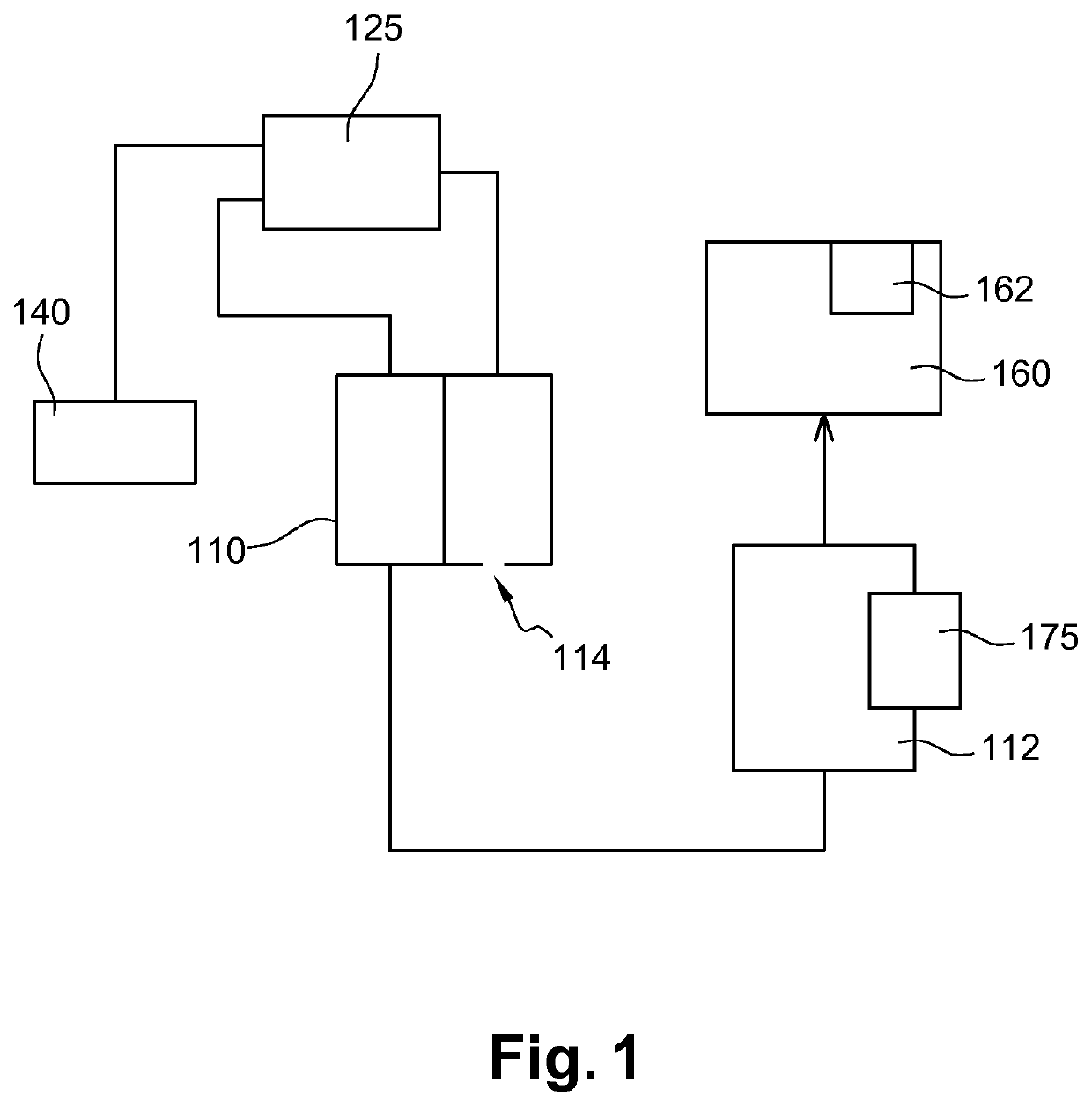
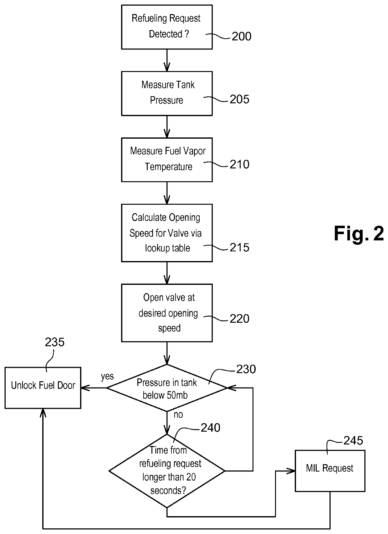
The present invention provides methods and assemblies for reducing the risk of corking or clogging during refueling operations in extreme conditions and avoiding expulsion of fuel towards the operator while opening the fuel cap. The invention includes an opening speed calculated to prevent coking of another valve in the fuel tank. A pressure sensor is in the tank to determine the safety of opening the fuel door without risk for the operator. A level sensor is used to fine-tune the valve opening speed. The invention also prevents damage to the fuel system and prolongs the life expectancy of the venting valves.

Problems solved by technology

An inconvenience is that when the pressure difference is high, the switch between the two stages may be too sudden resulting in corking.

Method used


Image

  • System and method for variation of the opening speed of a fuel tank valve
  • System and method for variation of the opening speed of a fuel tank valve
  • System and method for variation of the opening speed of a fuel tank valve

Examples


Embodiment Construction

[0039]The present invention will be described with respect to particular embodiments and with reference to certain drawings but the invention is not limited thereto but only by the claims. The drawings described are only schematic and are non-limiting. In the drawings, the size of some of the elements may be exaggerated and not drawn on scale for illustrative purposes. The dimensions and the relative dimensions do not correspond to actual reductions to practice of the invention.

[0040]Furthermore, the terms “first, second, third” and the like in the description and in the claims, are used for distinguishing between similar elements and not necessarily for describing a sequence, either temporally, spatially, in ranking or in any other manner. It is to be understood that the terms so used are interchangeable under appropriate circumstances and that the embodiments of the invention described herein are capable of operation in other sequences than described or illustrated herein.

[0041]Mo...


PUM

PropertyMeasurementUnit
Timeaaaaaaaaaa
Pressureaaaaaaaaaa
Pressureaaaaaaaaaa

Abstract

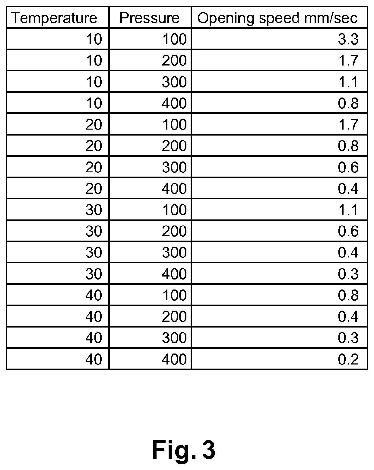
Method for controlling the opening speed of a valve connected between a fuel tank and a filter, and configured to relieve the pressure inside the fuel tank into the filter, the method comprising the steps of:— Measuring a pressure in the fuel tank,— Measuring or inferring a fuel vapor temperature in the fuel tank,— Calculating an opening speed as a function of the pressure and the fuel vapor temperature in the fuel tank,— Opening the valve at the calculated opening speed in order to avoid corking of another valve of the fuel tank connected between the valve and the fuel tank. Assembly for putting the method into practice

Description

TECHNICAL FIELD OF THE INVENTION[0001]The invention is related to isolation valves for fuel tanks in the automotive industryBACKGROUND OF THE INVENTION[0002]Fuel tank vapor and emission control systems are used to control the flow of fuel vapors from a vehicles fuel tank and also to control the relative pressure of the fuel tank. Vapors are vented to a canister or another vapor control structure, where hydrocarbon vapors are stored and which is also connected to the engine air inlet.[0003]Fuel tanks produce fuel vapor during various operating phases and theses vapors are directed to a canister or another component responsible for storing them, and then purging them regularly to the admission header of the engine. Periodic purging of stored vapors is necessary during the operation of the vehicle. In order to control the purge, the fuel system is operated to control the flow of vapor from the storage canister to the engine air inlet, and atmospheric air is admitted to purge the canist...

Claims


Application Information

Patent Timeline
IPC IPC(8): F02M25/08B60K15/05F02D41/00B01D46/42B01D46/44
CPCF02M25/0836B60K2015/0319B60K2015/03217B60K2015/0561B60K15/05B60K2015/03236B01D46/4272B01D2279/35B01D46/446B60K2015/0358F02D41/004F02D2200/0602F02D2200/0606B60K2015/03576B01D46/448B60K2015/03561B60K15/03504B60K15/03519F02D41/221F02M25/0809B60K2015/03302B60K2015/03514F02M2025/0845
Inventor GUIRY, MITOUNHILL, DAVID
Owner PLASTIC OMNIUM ADVANCED INNOVATION & RES SA
Learn More