Two-stage locking electric screwdriver

a screwdriver and two-stage locking technology, applied in the direction of screwdrivers, power-driven tools, wrenches, etc., can solve the problems of loose locking, loss of so-called clamping force, and almost unavoidable defects

Active Publication Date: 2017-01-31
HSU HSIU LIN
View PDF31 Cites 2 Cited by
  • Summary
  • Abstract
  • Description
  • Claims
  • Application Information

AI Technical Summary

Benefits of technology

[0013]The primary objective of the present invention is to provide a two-stage locking electric screwdriver, which, based on the design of an internal gear clutch with staggered internal teeth and interlaced cams, the inner ring orbit of the cam can firstly provide a torque for pre-locking, and during operation, when the cams on the inner and outer ring orbits interlace, a maximum torque will be generated for a perfect locking effect.
[0014]The second objective of the present invention is to provide a two-stage locking electric screwdriver, through which the torque can be directly modulated and the torsion spring can be replaced timely to substantially enhance the torque accuracy.
[0015]The third objective of the present invention is to provide a two-stage locking electric screwdriver, so as to dramatically reduce the number of parts to produce the electric screwdriver, and to reduce production cost and save power.

Problems solved by technology

On the other hand, during actual assembly operations, those charts, standards and testing results often cannot reflect the factors influencing the assembly, while the results are often used as the basis for the assembly operations.
Just because the locking assembly process is finished in a very short time, in the locking operation to bind elastic materials, defects are almost unavoidable.
When the elastic material has a plastic deformation, like a spring, even though the screw (bolt) is locked within its elastic limit, it may also cause looseness of the locking, i.e., loss of the so-called clamping force.
Based on the descriptions, the above FIG. 2 (B) means that, when the screw (bolt) is rotated in a very instant torque to reach the locking status, even if the torque is maintained within the tolerance range, the locking operation is actually incomplete and the screw (bolt) is not properly installed.
Hence it consumes more power.
This will increase the rotational weight and will consume more power.

Method used


Image

  • Two-stage locking electric screwdriver
  • Two-stage locking electric screwdriver
  • Two-stage locking electric screwdriver

Examples


Embodiment Construction

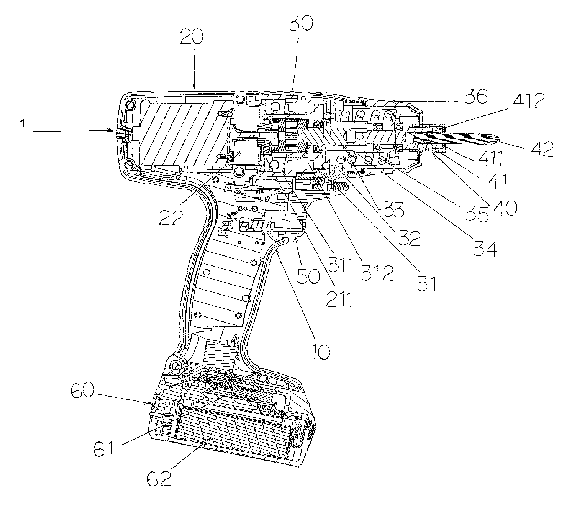
[0039]The electric screwdriver 1 is rechargeable, with a matching external enclosure 10. The enclosure 10 can be in any type, such as upright type, or gun type etc. The present embodiment takes the gun type as an example. Inside the enclosure 10, there are at least configurations including: a motor unit 20, an internal gear clutch unit 30, a screwdriver head unit 40, a trigger unit 50 and a controller unit 60.

[0040]The motor unit 20 further includes: a motor 21, an accelerator / supercharger 22. The motor 21 is preferably but not limited to a brushless motor, and the power outputting spin axis 211 has a going-through accelerator / supercharger 22, which includes one or more than one bearing (or sleeve) with certain proportional weight and is made of metallic material; in actual application, the accelerator / supercharger 22 is configured on the power outputting spin axis 211 of the motor 21, for the effect of slow start and accelerated running. With this, the power of the motor can be dou...


PUM


Abstract

A two-stage locking electric screwdriver, with its main improved features as follow: the electric screwdriver has pre-locking and locking functions; the torque settings of the electric screwdriver can be easily modulated, and meanwhile the torque accuracy and energy efficiency can be improved; the torque modulation type is external modulation, so that the torque modulation can be carried out externally and even the torsion spring can be replaced. Meanwhile, the component structures inside the electric screwdriver is improved through a design that the motor directly drives the clutch and then drive the screwdriver head unit, and that an internal gear clutch is used to replaced the gear unit and clutch unit, so that the number of parts is dramatically reduced to save production cost. During general rotation, the electric screwdriver will not drive the clutch unit, and when the torque jumps to the set value, the internal gear clutch rotates and generates a torque.

Description

BACKGROUND OF INVENTION[0001]1. Field of the Invention[0002]The present invention relates generally to an innovative electric screwdriver, and more particularly to a two-stage locking electric screwdriver with external torque modulation, featuring convenient modulation, accurate torque, lower power consumption and minimal number of parts.[0003]2. Description of Related Art[0004]The technique of screw (bolt) locking is playing a significant role in various industrial fields and modern technologies. The screw (bolt) assembly technique is particularly important in the automobile, aerospace and bolt manufacturing fields[0005]SCHATZ is a company with more than 50 years of technical experience and has long been engaged in the development of solutions for assembly and quality assurance of various bolts. The company has set a benchmark for the industry, and its technological level has become national or even international standards and guidelines; Doctor Volker Schatz authored a book named ...

Claims


Application Information

Patent Timeline
Patent Type & Authority Patents(United States)
IPC IPC(8): B25B21/00B25F5/00B25B23/14
CPCB25F5/001B25B21/008B25B23/141
Inventor HSU, HSIU-LIN
Owner HSU HSIU LIN
Why Eureka
Try Eureka