Flow directing device for a cooking appliance

a technology of flow directing device and cooking utensils, which is applied in the direction of domestic heating details, lighting and heating apparatus, domestic heating, etc., can solve the problems of reducing the effectiveness of the circulation of the cooking chamber atmosphere by the fan wheel, and achieve the effect of improving the effectiveness of the circulation within the interior of the cooking utensils

Active Publication Date: 2017-01-31
RATIONAL AG
View PDF51 Cites 1 Cited by
  • Summary
  • Abstract
  • Description
  • Claims
  • Application Information

AI Technical Summary

Benefits of technology

[0009]The object of the embodiments of the present invention is therefore to further develop the generic flow directing device in such a manner that it overcomes the disadvantages of the prior art. In particular, the effectiveness of a circulation within the interior of a cooking appliance should be improved.
[0025]The embodiments of the present invention are thus based on the surprising finding that on the one hand, at least one first stationary flow directing member, for example, in the form of a standard air directing plate, is used in the interior of a cooking appliance, in order to separate the interior into a pressure chamber and a cooking chamber, wherein the first flow directing member leaves free a central suction port and at least one blow-off port on the edge side, and is affixed to the wall of the interior, while on the other hand, at least one second flow directing member is used, which fulfils or performs the function of a nozzle and which extends from a fan wheel in the pressure chamber, to which it is attached or molded together, through the suction port of the first flow directing member, so that the second flow directing member turns with the fan wheel. In a particularly advantageous manner, the nozzle, in particular, in the form of a ring is attached to a support ring for the blades of a radial fan, or is formed from a plurality of blade extensions. In any case, due to the nozzle, which rotates with the fan wheel, a radial flow is avoided in the suction area of the fan wheel, and thus, a short-circuit flow is also prevented. This increases the efficiency of the fan wheel and reduces the sensitivity of the entire cooking appliance to size tolerances.
[0026]Because radial fans are in principle relatively compact and are highly efficient, they are preferably used with a flow directing device according to the embodiments of the present invention. The high pressure area (the pressure side of the fan) and the suction area (the suction side of the fan) of a radial fan are relatively close to each other, so that due to the nozzle on the radial fan, a significant increase in fan capacity or reduction in the consumption capacity of the fan motor, is provided.
[0028]Due to the size and geometry of the nozzle, further advantages can be attained, namely for the targeted directing of the flow. If the nozzle extends, on the one hand, in the pressure chamber into the area in which the blades of the radial fan create a pressure increase, the quantity of short-circuit flow is further reduced. If, on the other hand, the nozzle extends into the cooking chamber, an eddy formation in the suction area of the radial fan is reduced.
[0029]It is preferred according to the embodiments of the present invention that a third flow directing member is also used, which ensures that in the blow-off area of the radial fan, the pressure chamber comprises a chamber that extends radially outwards, so that the third flow directing member acts as a diffuser and further reduces the occurrence of short-circuit flows. The third flow directing member can be realised together with the first flow directing member.

Problems solved by technology

However, the disadvantage here is that a gap must be present at all times between a rotating fan wheel in the pressure chamber on the one hand, and the suction nozzle on the air directing plate on the other, in order to avoid damage.
Thus, the short-circuit flow runs transverse to the main flow in the suction area of the fan wheel, so that it narrows the main flow and can itself cause a displacement and swirling of the main flow, which leads to an overall reduction in the effectiveness of the circulation of cooking chamber atmosphere by the fan wheel.

Method used


Image

  • Flow directing device for a cooking appliance
  • Flow directing device for a cooking appliance
  • Flow directing device for a cooking appliance

Examples


Embodiment Construction

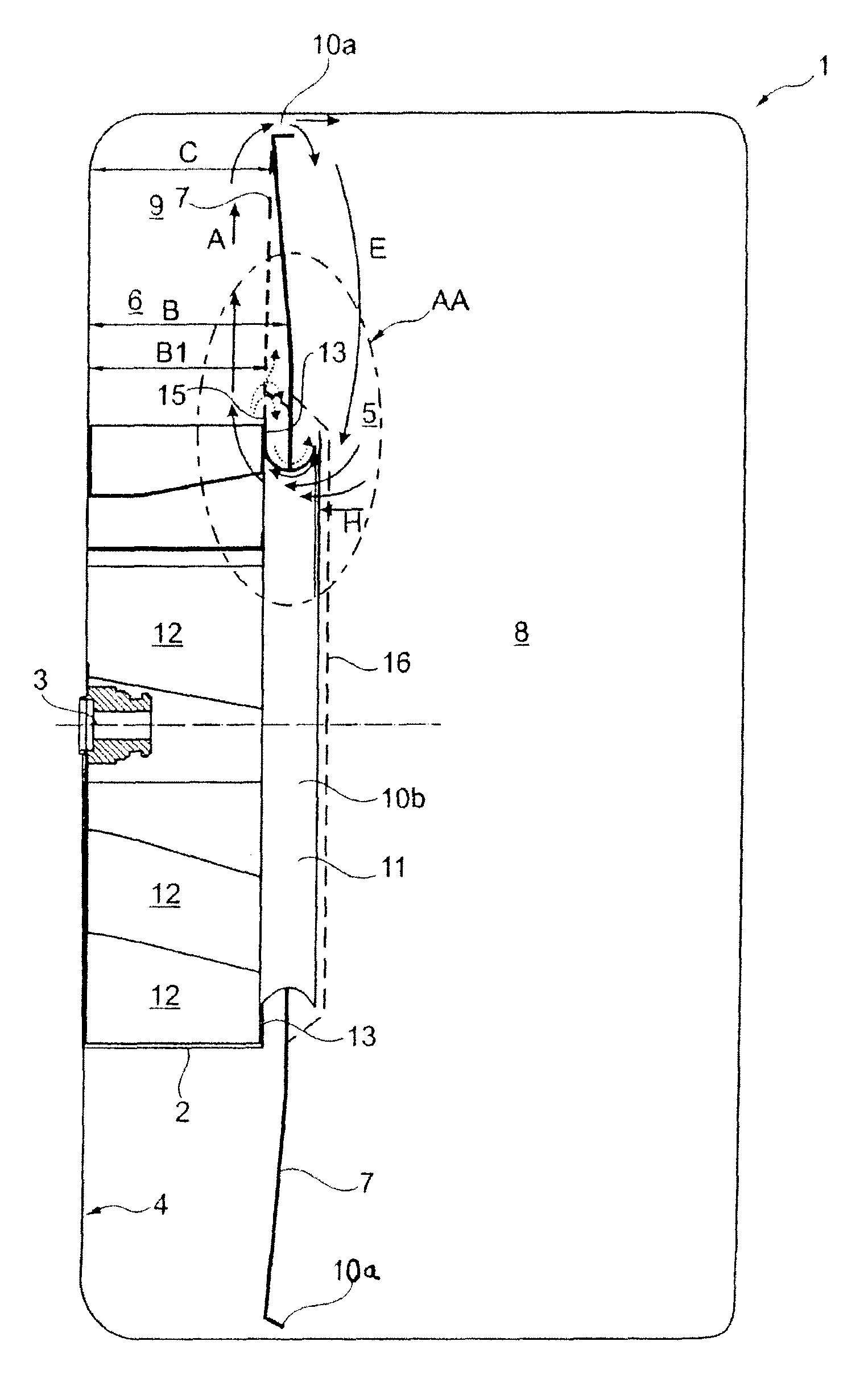
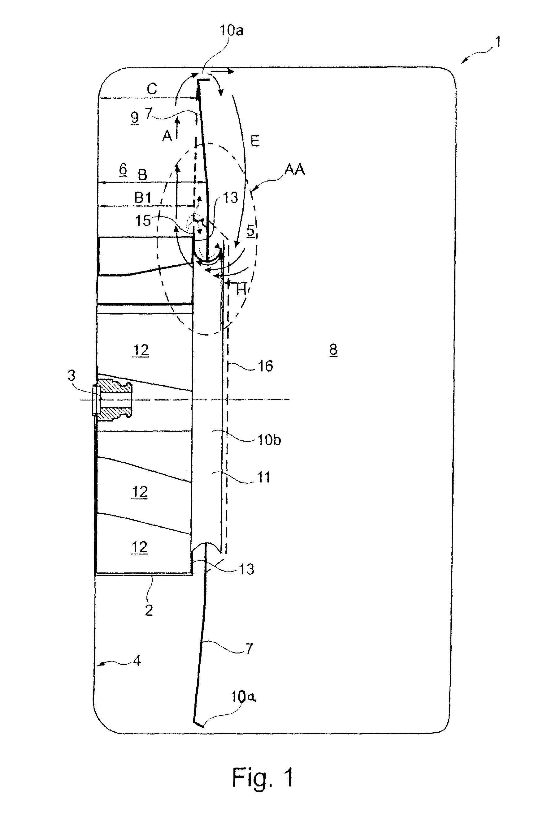
[0034]A cooking appliance according to the embodiments of the present invention comprises, as is shown in FIG. 1, an interior 1, which houses a fan wheel 2 in the form of a radial fan wheel. The fan wheel 2 is mounted on a drive shaft 3 of a motor (not shown), which is located outside the interior 1. If, as an alternative, the motor were to be located inside the interior 1, then cooling measures would be required.

[0035]Although in principle, an axial fan could also be used, a radial fan has the advantage that atmosphere, which is brought into rotation, in particular cooking chamber atmosphere, does not impact against a rear wall 4 of the interior 1, but is instead deflected into the fan wheel 2. As a result, the arrangement is compact and has a high degree of efficiency.

[0036]The fan wheel 2 sucks in atmosphere centrally, namely, from a suction area 5, (see the suction flow E in FIG. 1), and blows it off radially, namely, into a blow-off area 6, (see the blow-off flow A in FIG. 1). ...


PUM


Abstract

A cooking appliance including an interior, a fan mechanism having at least one fan wheel in the interior, at least one first flow directing member for subdividing the interior into a pressure chamber that houses the fan wheel and a cooking chamber, in which the first flow directing member includes at least one suction port for sucking atmosphere from the cooking chamber into the pressure chamber when the fan wheel is in operation and at least one blow-off port for blowing atmosphere from the pressure chamber into the cooking chamber when the fan wheel is in operation; and at least one second flow directing member that is included with the fan mechanism in the area of the suction port of the first flow directing member in order to improve the flow from the cooking chamber into the pressure chamber by forcing an axial main flow H in the suction zone of the fan mechanism, where the second flow directing member performs a nozzle function, extends from the fan mechanism into the cooking chamber, and overlaps the edge of the suction port of the first flow directing member, and where the first flow directing member extends into the second flow directing member.

Description

CROSS-REFERENCE TO RELATED APPLICATIONS[0001]This application is a national stage application of International Application No. PCT / EP2009 / 064020, filed on Oct. 23, 2009, which claims the benefit of German Patent Application No. DE 10 2008 053 145.6, filed on Oct. 24, 2008, the entire contents of both applications are incorporated herein by reference in their entireties.BACKGROUND OF THE INVENTION[0002]Field of the Invention[0003]Embodiments of the present invention relate to a flow directing device for a cooking appliance with a fan mechanism, which comprises at least one fan wheel in an interior of the cooking appliance for circulating atmosphere, comprising at least one first flow directing member for subdividing the interior into a pressure chamber with the fan wheel and a cooking chamber, wherein the first flow directing member leaves free at least one suction port for sucking atmosphere from the cooking chamber into the pressure chamber in the area of the fan wheel and at least...

Claims


Application Information

Patent Timeline
Patent Type & Authority Patents(United States)
IPC IPC(8): F24B1/00F24C15/32
CPCF24C15/322F24C15/32
Inventor CLAUSSEN, ERNSTHYLLA, JOACHIM J.WITT, OLIVERXIA, YINGANHERNER, MICHAELSCHREINER, THOMASKURTH, ROBERTRING, LEONHARDPAINTNER, ALDO
Owner RATIONAL AG
Why Eureka
Try Eureka