
Embolization device and a method of using the same

a technology of embolization device and embolization method, which is applied in the direction of dilators, prostheses, blood vessels, etc., can solve the problems of vascular spasm, paralysis or other adverse events, toxic to tissue, etc., and achieve the effect of reducing increasing the flexibility of the space-occupying devi

Inactive Publication Date: 2017-02-07
ENDOLOGIX LLC
View PDF177 Cites 13 Cited by
  • Summary
  • Abstract
  • Description
  • Claims
  • Application Information

AI Technical Summary

Benefits of technology

The patent describes a device for filling abnormal voids in the body, such as an aneurysm, which involves a flexible leader and at least one non-expandable space-occupying element connected to it. The device has a binding agent that attaches the two parts together, reducing flexibility but increasing pushability during deployment. The binding agent can be exposed to a softening agent to restore flexibility. A method for placing and deploying the device is also described. The technical effects of the patent are improved properties of the space-occupying device, such as reduced flexibility in the deployed state and increased pushability during deployment, which can aid in ejection from the delivery catheter.

Problems solved by technology

Cragg et al. teach that these solvents can be toxic to tissue and may cause vascular spasms.
Using liquid-solidifying agents in active vessels also carries a high risk that the agents will flow downstream creating emboli or flow into collateral vessels (e.g., lumbar arteries), which may lead to paralysis or other adverse events.
Shifting of the microcoil can lead to recanalization of the aneurysm.
Another disadvantage of microcoils is that they are not easily retrievable.
The expansion of the device after deployment reduces the volumetric precision with which the sac can be filled.
If the volume of the expanded device is too large, the device can press against the inner side of weakened aneurysm wall and outer side of prosthesis, altering flow within the prosthesis and increasing the risk of rupture of the aneurysm.
If the volume of the expanded device is too small, the prosthesis can still alter its position and dislodge or migrate.

Method used


Image

  • Embolization device and a method of using the same
  • Embolization device and a method of using the same
  • Embolization device and a method of using the same

Examples


Embodiment Construction

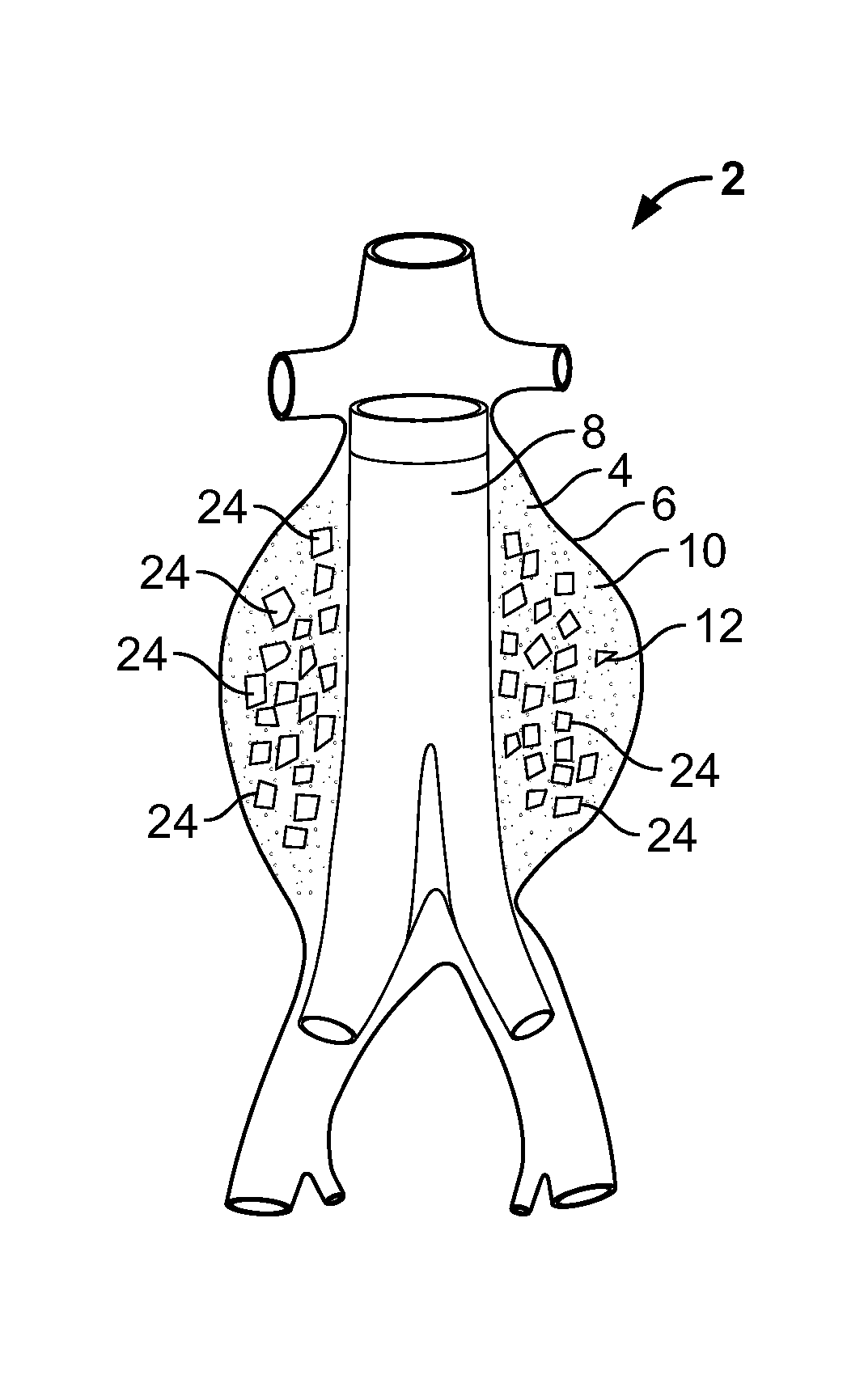
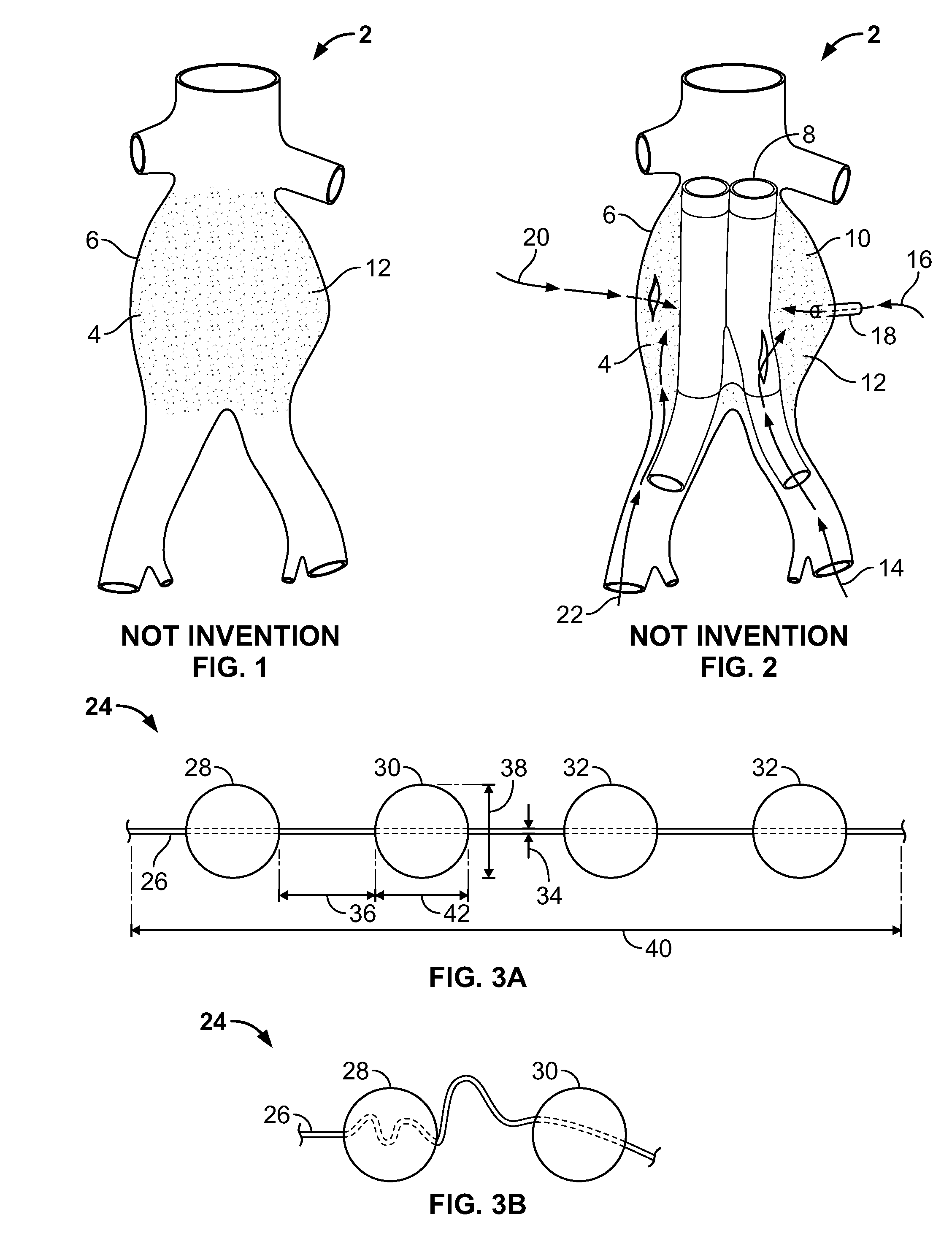
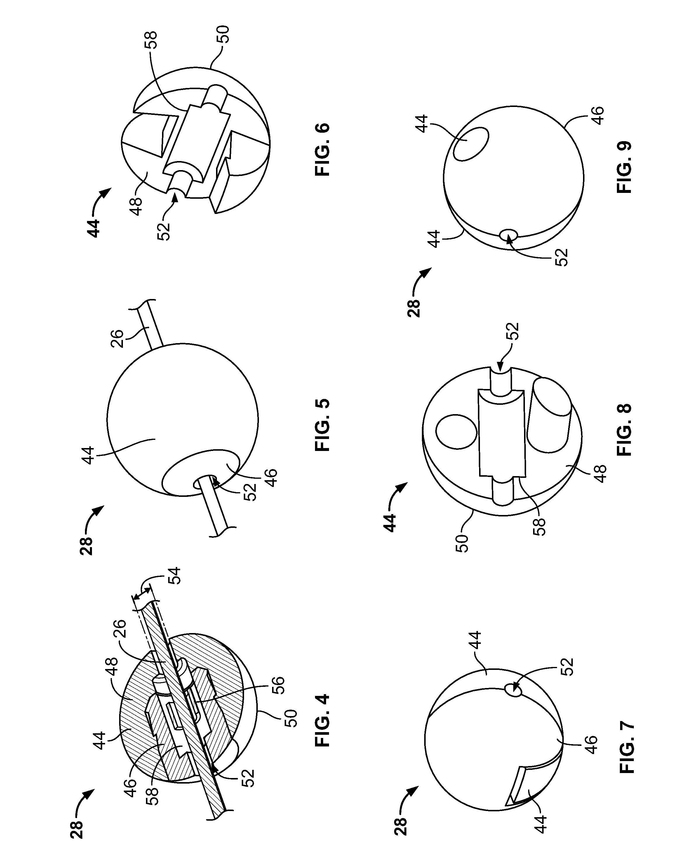
[0052]FIG. 3a illustrates an embodiment of a vascular embolization or occlusion device 24 having a flexible leader 26 that can be connected to a first non-expandable space-occupying element 28 and a second non-expandable space-occupying element 30. Additional non-expandable space-occupying elements 32 can also be connected to the leader 26 and provided in various lengths, depending on the typical volume of the sac 10 to be filled. The leader 26 can pass through the elements 28, 30 and 32. The leader 26 can be fixed to the elements 28, 30 and 32, or the elements 28, 30 and 32 can slide freely over the leader 26. As illustrated in FIG. 3b, the leader 26, even if secured within an element 28, 30, or 32, can flex and bend within each element 28, 30 or 32, or between the elements 28, 30 and 32.

[0053]The leader 26 can be a suture, preformed resilient structure, poppet, wire, fiber, monofilament, rail, or a woven thread or other combination thereof. The leader 26 can be completely separate...


PUM


Abstract

Space-occupying devices for treating voids within the body are disclosed. The devices can have multiple elements connected to a flexible leader. The devices can be coated by a binding agent. The devices can also be fillable. Methods of making and using the devices are also disclosed.

Description

CROSS-REFERENCE TO RELATED APPLICATIONS[0001]This application is a continuation of U.S. patent application Ser. No. 10 / 622,437, filed on Jul. 18, 2003, now abandoned, the content of which is incorporated herein by reference in its entirety.BACKGROUND OF THE INVENTION[0002]Field of the Invention[0003]The present invention relates generally to a device for filling and / or stabilizing the void within an anatomical organ of the body, particularly within the vasculature, and methods for making and using the device.[0004]Description of the Related Art[0005]An aneurysm is an abnormal dilatation of a biological vessel. Aneurysms can alter flow through the affected vessel and often decrease the strength of the vessel wall, thereby increasing the vessel's risk of rupturing at the point of dilation or weakening. FIG. 1 illustrates an abdominal aorta 2 with a sacular aneurysm 4 having an aneurysm wall 6. FIG. 2 illustrates the abdominal aorta 2 with a vascular prosthesis 8 implanted to treat the...

Claims


Application Information

Patent Timeline
Patent Type & Authority Patents(United States)
IPC IPC(8): A61M29/00A61B17/12A61F2/07A61L31/04A61F2/88A61F2/06
CPCA61B17/12118A61B17/12022A61B17/12163A61F2/07A61F2/88A61L31/044A61F2002/075A61F2220/0091A61F2230/001A61F2230/0019A61F2230/0021
Inventor FOGARTY, THOMAS J.DREWS, MICHAEL J.MODESITT, D. BRUCEHOLMGREN, NEIL BRUCEWILLIS, DAVID B.
Owner ENDOLOGIX LLC
Learn More