Active electromechanical suspension and power generation system using an acceleration controller

an electromechanical suspension and power generation technology, applied in the direction of suspensions, vehicle components, transportation and packaging, etc., can solve the problems of reducing the efficiency potential of these vehicles, reducing the efficiency of these vehicles, and reducing the weight and so as to improve the damping method, reduce the weight and size of the suspension, the effect of reducing the weight and siz

Active Publication Date: 2017-02-07
JOHNSON JONATHAN
View PDF1 Cites 1 Cited by
  • Summary
  • Abstract
  • Description
  • Claims
  • Application Information

AI Technical Summary

Benefits of technology

[0003]It is an object of the present invention to overcome the shortcomings of the traditional suspension by providing an improved damping method. Using a geared motor and an acceleration control unit instead of the usual hydraulic device, the present invention can convert the kinetic energy of the road and the energy stored in the spring into electricity. It can also assist the spring, when necessary, during adverse road conditions or fast cornering; thus, reducing the weight and size of the suspension by eliminating the need for parts with similar functions, like a stabilizer bar. Moreover, the invention uses simple parts that are easy to replace and manufacture.

Problems solved by technology

However, the modern vehicle suspension has not taken advantage of this trend to any significant degree.
In the past, various electronic systems have been introduced to aid in the function of a suspension, but they often added weight and used valuable space.
Although many drivers continue to transition to Electric Vehicles, the use of outdated suspension designs have held back the efficiency potential of these vehicles.
While the spring's storage and release of energy has show to be useful, the shock absorber's heat dissipation has not.
Actually, this obvious waste of energy is one of the many flaws associated with vehicle suspensions and has been the driving force behind several other patents.

Method used


Image

  • Active electromechanical suspension and power generation system using an acceleration controller
  • Active electromechanical suspension and power generation system using an acceleration controller
  • Active electromechanical suspension and power generation system using an acceleration controller

Examples


Embodiment Construction

[0014]The present invention can best be understood by associating descriptions to some of the possible applications; hence, the following description will explain the attached drawings in detail.

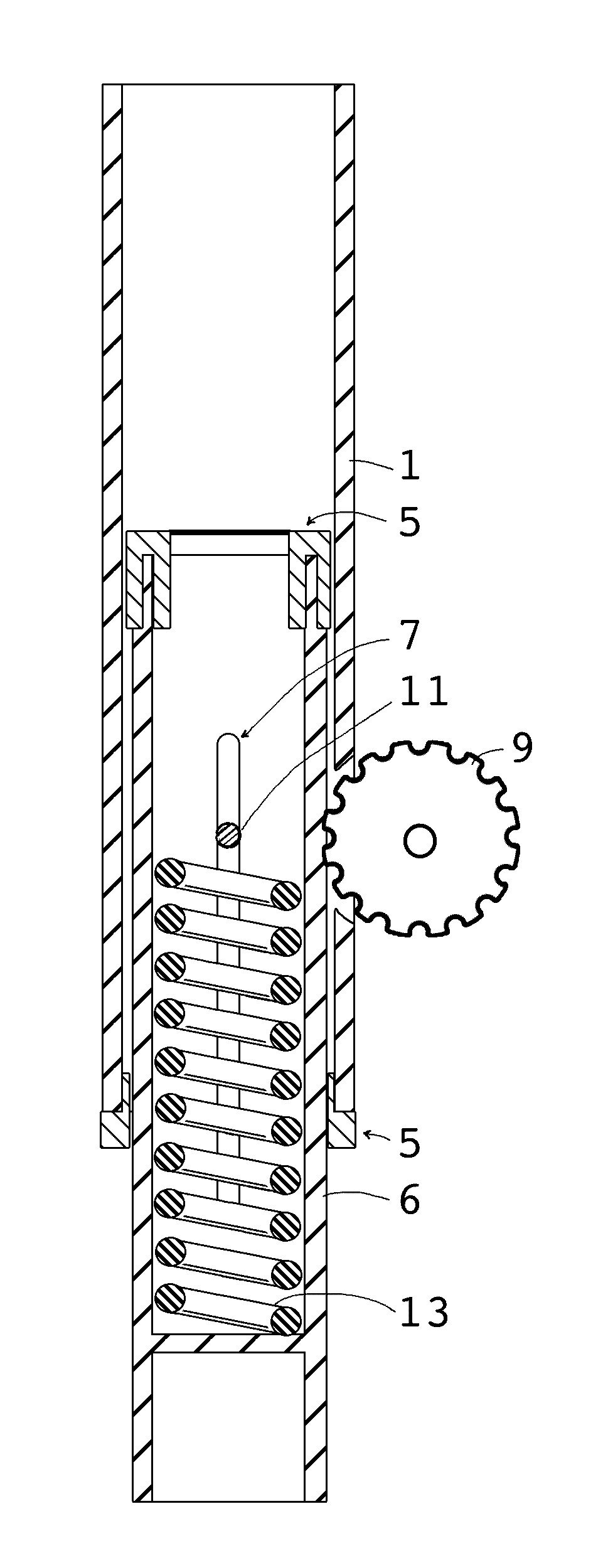
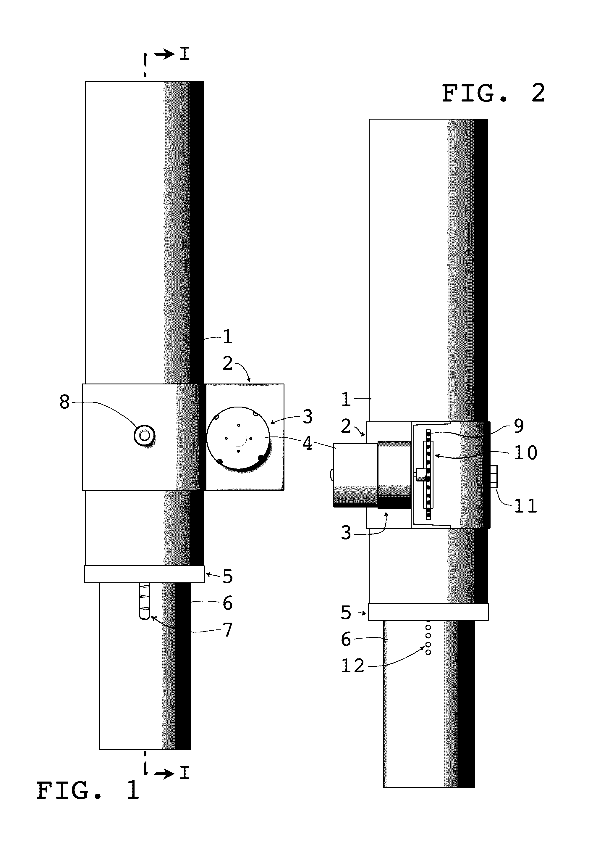
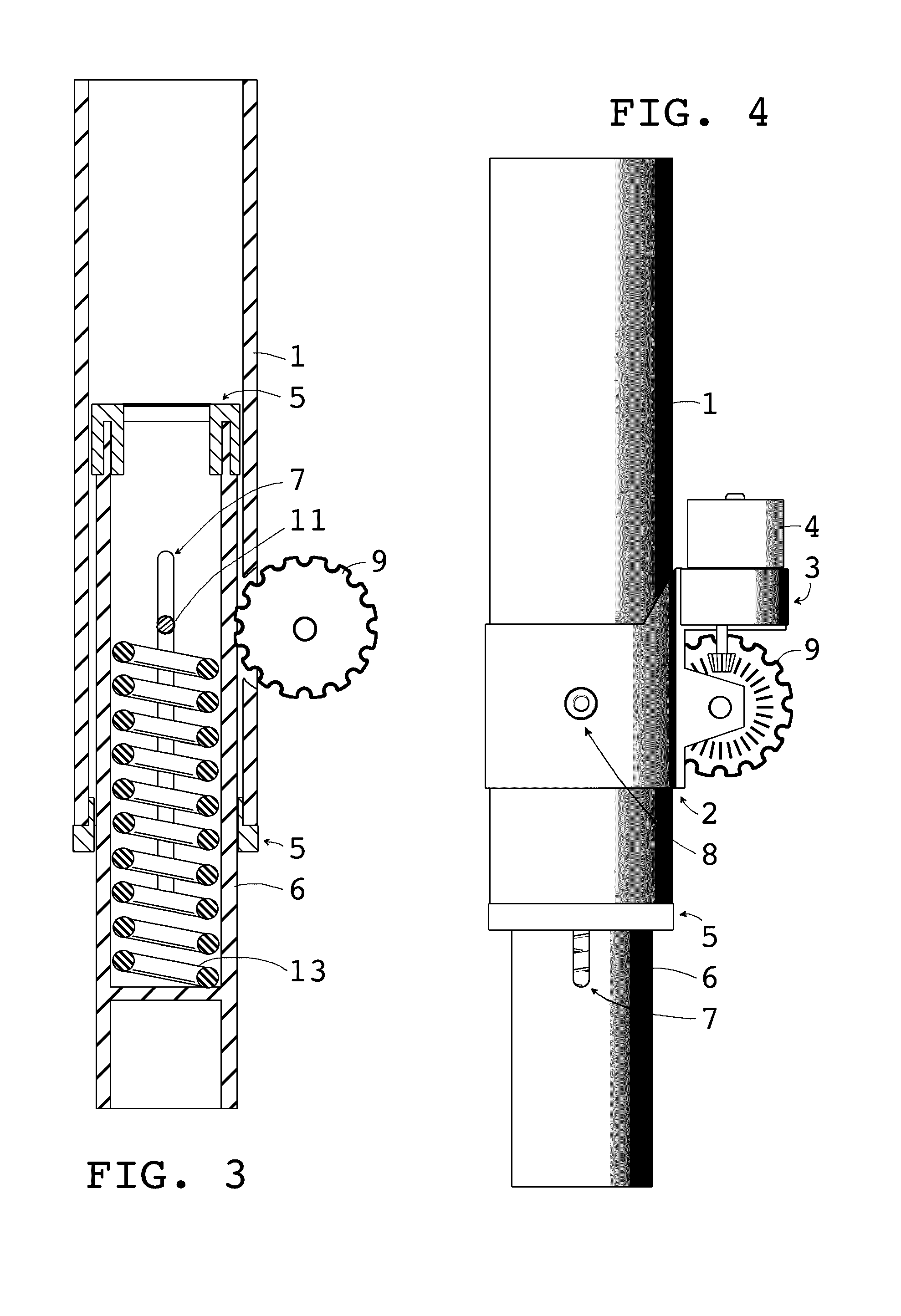
[0015]FIG. 1 shows a simplified embodiment of the present invention displaying a structure with the most potential for common use. The primary tube (1) would be attached to the vehicle chassis like a mounted fork or shock absorber. The secondary tube (6) would also be attached with an appropriately equivalent mounting fixture. The motor (4) and it's gearbox (3) use a special mount (2) that is bolted (8) through the primary tube (1). This keeps the motor in the proper location for its function as an active dampener, and still allows for it to be serviceable. The next thing to note is the visible flange bearing (5) and the opening (7) showing the internal spring.

[0016]FIG. 2 is the front view of FIG. 1 and shows the sprocket (9) that fits into the slot (10) that is cut into the primary tube (1...


PUM


Abstract

The invention disclosed herein consists of an active electromechanical suspension and power generation system using an accelerometer connected to a controller. The electromechanical suspension consists of a geared motor and spring, which are used to isolate the vehicle chassis from the wheel, with the motor also functioning as a generator. The controller uses a 3-axis accelerometer's data to determine which direction to turn the motor and when to turn it.

Description

BACKGROUND OF THE INVENTION[0001]Electronics are often used to increase the speed and decrease the weight of modern vehicles. However, the modern vehicle suspension has not taken advantage of this trend to any significant degree. In the past, various electronic systems have been introduced to aid in the function of a suspension, but they often added weight and used valuable space. The engineers seemingly molding their design to produce comfort for luxury vehicles instead of increasing vehicle performance. Although many drivers continue to transition to Electric Vehicles, the use of outdated suspension designs have held back the efficiency potential of these vehicles. This would suggest a need to redesign the basic parts of a suspension by function.[0002]The basic function of a suspension is to reduce the amount of vibration while maintaining vehicle performance, which usually translates to a spring and shock absorber setup. The spring takes the initial shock of various road conditio...

Claims


Application Information

Patent Timeline
Patent Type & Authority Patents(United States)
IPC IPC(8): B60G17/02B60G17/016
CPCB60G17/0164B60G17/02B60G13/18B60G17/0162B60G2300/50B60G2300/60B60G2600/182
Inventor JOHNSON, JONATHAN DAVID
Owner JOHNSON JONATHAN
Why Eureka
Try Eureka