Portable brush cutter

a brush cutter and portability technology, applied in the direction of mechanical actuators, mechanical components, couplings, etc., can solve the problems of shortening the product life, deteriorating operability, increasing fatigue, etc., and achieves the effect of suppressing unpleasant torsional vibration of the transmission shaft, simple structure and improved durability and the lik

Active Publication Date: 2020-09-15
YAMABIKO CORP
View PDF8 Cites 0 Cited by
  • Summary
  • Abstract
  • Description
  • Claims
  • Application Information

AI Technical Summary

Benefits of technology

[0011]Meanwhile, when a one-way clutch is used, as compared to the case when a torsion coil spring is used, the structure is simpler, but the problem in durability still exists in that the one-way clutch is vulnerable to the stress in the radial direction, and thus easily breaks due to radial vibration of the transmission shaft.
[0012]Further, in the conventional portable brush cutter described in JP 2003-88220 A above, there has been a difficulty in reducing the weight and size of the portable brush cutter, because, for example, a sleeve member with a spline formed on its inner periphery is pressed into a space between the one-way clutch and the transmission shaft, and thus the number of components is increased so that the structure becomes complicated, and also the sleeve member needs to have some thickness in the portion of the spline on the transmission shaft.
[0013]The present disclosure has been made in view of the aforementioned circumstances, and provides a portable brush cutter with reduced weight and size due to its simple structure with a small number of components that is capable of improving durability and the like as well as effectively suppressing torsional vibration of the transmission shaft.
[0014]According to an embodiment of the present disclosure, there is provided a portable brush cutter basically including a cutting blade that rotates about a rotating shaft, and a transmission shaft that is positioned between an output shaft of a prime mover and the rotating shaft and couples them together when they are driven. Further, in the portable brush cutter, the rotation of the output shaft of the prime mover is transmitted to the cutting blade via a rotation transmission path, a one-way clutch to prevent generation of torsional vibration in the rotation transmission path is interposed between the output shaft and the transmission shaft or between the rotating shaft and the cutting blade, and bearings are adjacently mounted on the opposite sides of the one-way clutch.
[0023]According to the present disclosure, the torsional vibration of the transmission shaft is suppressed by the one-way clutch disposed in the rotation transmission path, thereby effectively suppressing unpleasant torsional vibration of the transmission shaft transmitted to the hands of the operator. Further, with the bearings adjacently mounted on the opposite sides of the one-way clutch, the radial load on the one-way clutch can be effectively suppressed, and as a result, the one-way clutch does not easily break so that the durability and the like can be improved.
[0024]Further, in that case, the transmission shaft or the rotating shaft is directly fit-inserted into the one-way clutch and the bearings, so that the structure is simple with a small number of components, thereby enabling the weight and size of the portable brush cutter to be reduced as compared to conventional ones.

Problems solved by technology

Such vibration may not only cause abrasion of components in an early stage, thereby shortening the product life, but also cause deterioration of the operability and an increase in fatigue.
Therefore, it is an important issue to prepare a vibration-proof measure to suppress such vibration in the portable brush cutter.
However, although the aforementioned conventional vibration-proof measures that use a torsion coil spring or one-way clutch can provide the vibration-proof effect to some extent, the effect is still insufficient.
For example, when a torsion coil spring is used, the torsion coil spring is elastically deformed (twisted) depending on the twisting direction or the magnitude of twist (angle of torsion) of the transmission shaft, and thus there has been a problem in durability in that the torsion coil spring is easily worn out (that is, the spring force is deteriorated) or broken.
There have also been problems such as an increase in the production cost due to an increase in number of components, and an increase in weight due to the complicated and enlarged structure.
Meanwhile, when a one-way clutch is used, as compared to the case when a torsion coil spring is used, the structure is simpler, but the problem in durability still exists in that the one-way clutch is vulnerable to the stress in the radial direction, and thus easily breaks due to radial vibration of the transmission shaft.
Further, in the conventional portable brush cutter described in JP 2003-88220 A above, there has been a difficulty in reducing the weight and size of the portable brush cutter, because, for example, a sleeve member with a spline formed on its inner periphery is pressed into a space between the one-way clutch and the transmission shaft, and thus the number of components is increased so that the structure becomes complicated, and also the sleeve member needs to have some thickness in the portion of the spline on the transmission shaft.

Method used


Image

  • Portable brush cutter
  • Portable brush cutter
  • Portable brush cutter

Examples


Embodiment Construction

[0028]An embodiment of the present disclosure will be described below with reference to the drawings.

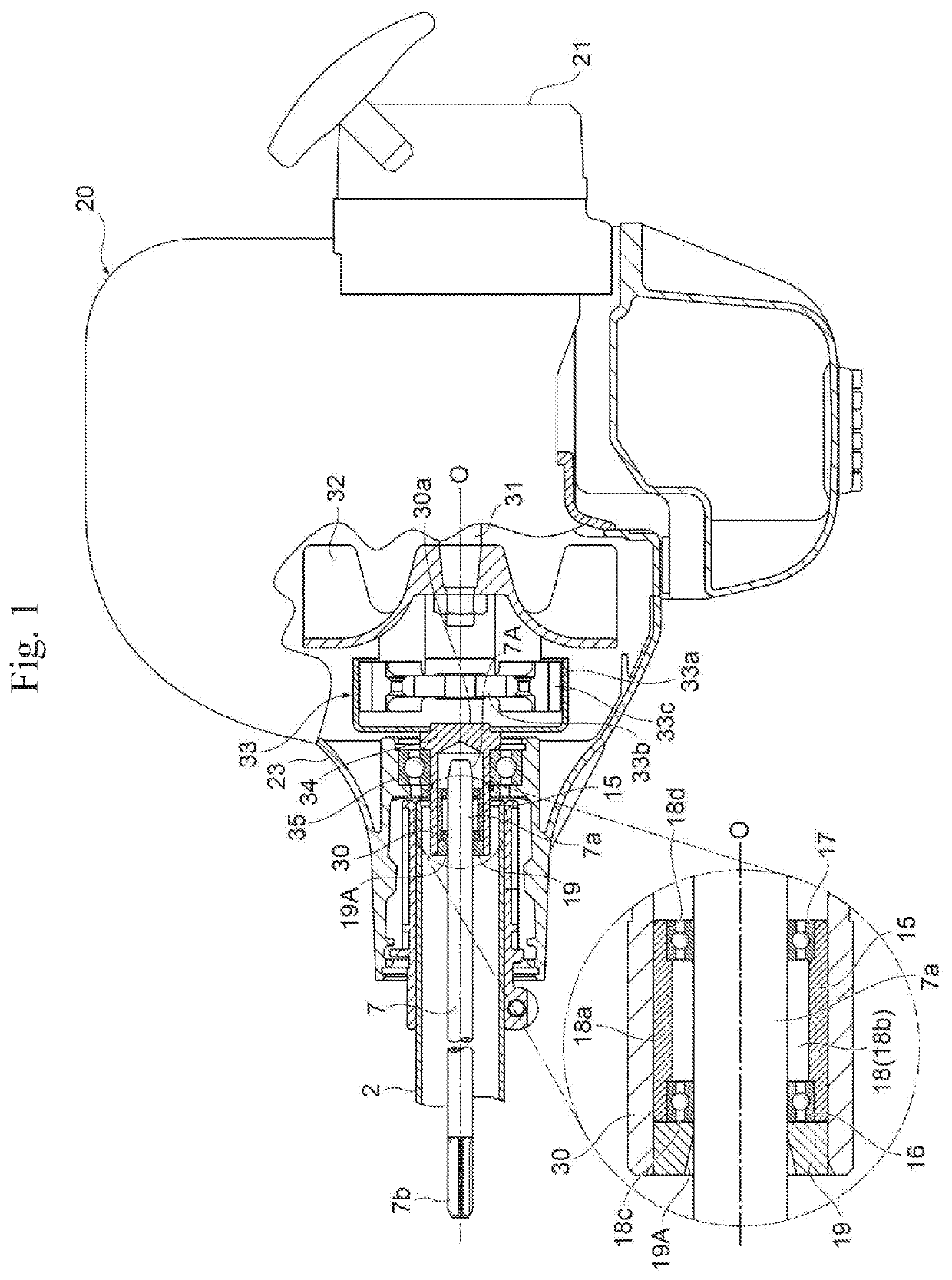
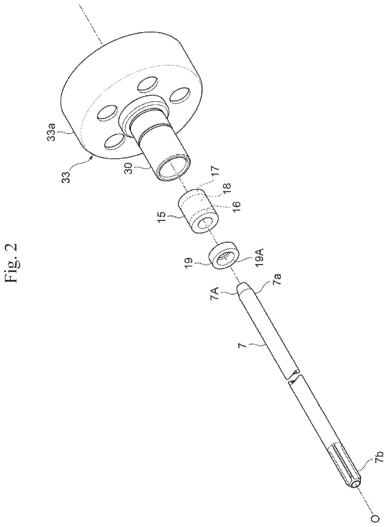
[0029]FIG. 1 is a partial cross-sectional view showing the main part of an embodiment of a portable brush cutter according to the present disclosure, and FIG. 2 is an exploded perspective view showing the main part of the portable brush cutter shown in FIG. 1.

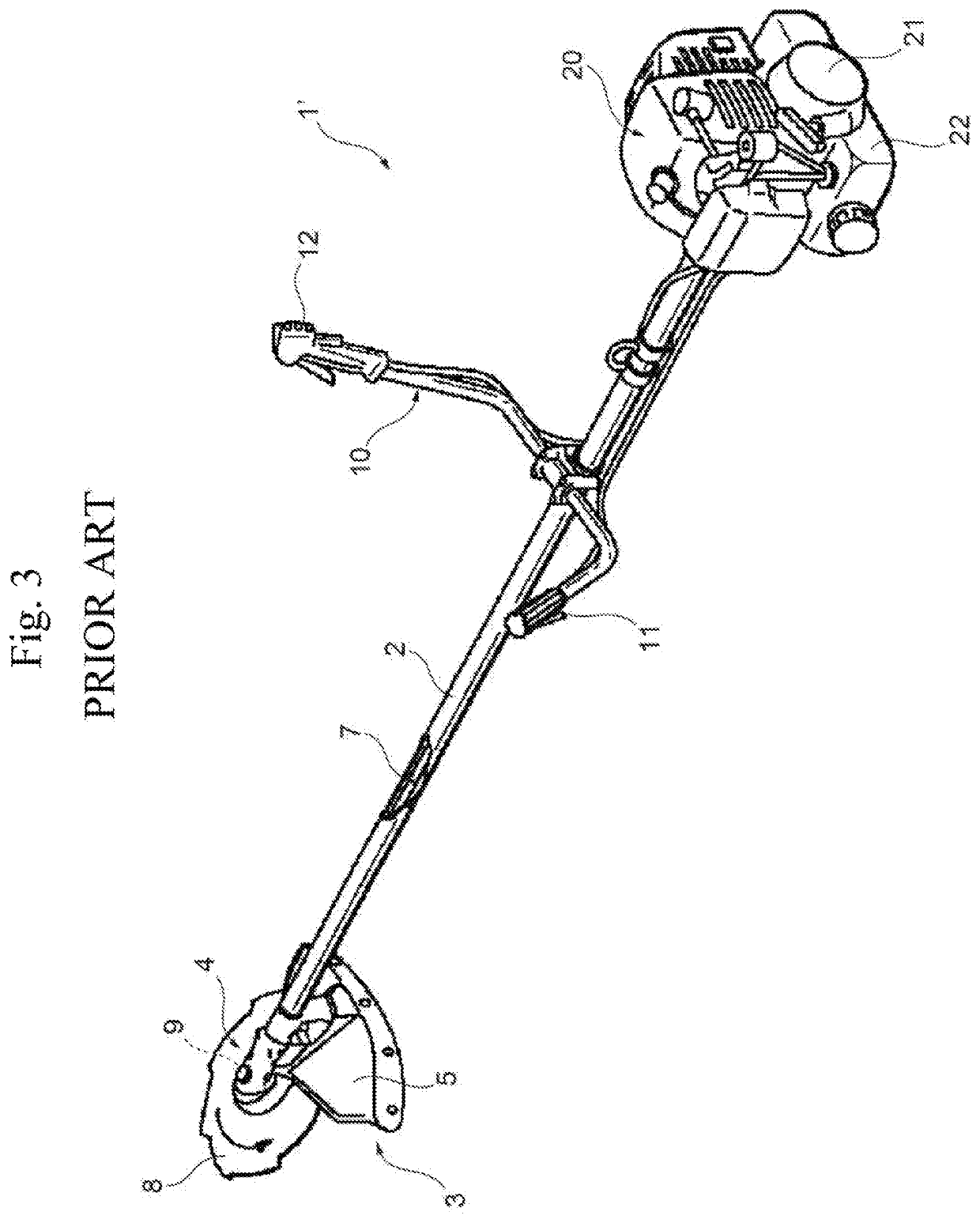
[0030]A portable brush cutter 1 of an embodiment shown in the drawings has substantially the same overall configuration as that of the aforementioned portable brush cutter 1′ shown in FIG. 3 and includes: a cutting blade operating unit 3 that has a cutting blade 8 provided rotatably about a rotating shaft 9, a gear box 4, and the like, at the front end of an operating rod 2 thereof; an internal combustion engine (air-cooled small two- or four-stroke cycle gasoline engine) 20 provided with a centrifugal clutch 33 for driving the cutting blade 8 via a transmission shaft 7 mounted inside the operating rod 2, and the like, attached ...


PUM


Abstract

Provided is a portable brush cutter with reduced weight and size due to its simple structure with a small number of components that is capable of improving durability and the like as well as effectively suppressing torsional vibration of a transmission shaft. In the portable brush cutter, a one-way clutch to prevent generation of torsional vibration in a rotation transmission path is interposed between an output shaft and a transmission shaft, and bearings are adjacently mounted on the opposite sides of the one-way clutch.

Description

CROSS REFERENCE TO RELATED APPLICATIONS[0001]The present application claims priority from Japanese patent application JP 2016-209463 filed on Oct. 26, 2016, the content of which is hereby incorporated by reference into this application.BACKGROUNDTechnical Field[0002]The present disclosure relates to a portable brush cutter, in particular, a portable brush cutter in which a one-way clutch is disposed in a rotation transmission path through which the rotation of an output shaft of a prime mover is transmitted to a cutting blade.Background Art[0003]FIG. 3 shows an example of conventional portable brush cutters. A portable brush cutter 1′ shown as the conventional example includes a cutting blade operating unit 3 that has a circular saw cutting blade 8 provided rotatably about a rotating shaft 9, a gear box (bevel gear unit) 4, a safety cover 5, and the like, at the front end of an operating rod 2 thereof. The portable brush cutter 1′ also has attached thereto, at the rear end of the op...

Claims


Application Information

Patent Timeline
Patent Type & Authority Patents(United States)
IPC IPC(8): A01D34/90F16D13/14F16D41/064F16D43/04A01D34/76A01D101/00
CPCA01D34/90A01D34/905A01D34/76F16D13/14F16D41/064F16D2300/22A01D2101/00F16D43/04A01G3/0535
Inventor SUGIYAMA, MIKIO
Owner YAMABIKO CORP
Why Eureka
Try Eureka