
Magnetic bearing for a turbomachine

a technology of magnetic bearing and turbomachine, which is applied in the direction of bearings, dynamo-electric machines, shafts, etc., can solve the problems of affecting the performance of the motor, so as to reduce the weight and size of the components, reduce the total overhang, and the effect of less tim

Active Publication Date: 2021-05-11
NUOVO PIGNONE TECH SRL
View PDF16 Cites 0 Cited by
  • Summary
  • Abstract
  • Description
  • Claims
  • Application Information

AI Technical Summary

Benefits of technology

The patent describes a way to make a magnetic bearing in a turbomachine that also acts as an impeller for cooling fluid. This means that the rotor of the bearing can also rotate, which reduces the need for a separate impeller and makes the machine lighter and smaller. It also makes assembly faster and easier.

Problems solved by technology

In addition to the heat generated by electrical loss mechanisms, operating the motorcompressor device at high speeds increases frictional losses generated by the rotating components.
If this heat is not properly dissipated, it negatively affects the performance of the motor and can damage the insulation of the stator.
Increased temperatures can also adversely affect the rotor-bearing systems of both the compressor and motor, thus leading to bearing damage and / or failure.

Method used


Image

  • Magnetic bearing for a turbomachine
  • Magnetic bearing for a turbomachine
  • Magnetic bearing for a turbomachine

Examples


Embodiment Construction

[0016]The following description of exemplary embodiments refer to the accompanying drawings. The same reference numbers in different drawings identify the same or similar elements. The following detailed description does not limit embodiments of the invention. Instead, the scope of embodiments of the invention is defined by the appended claims.

[0017]Reference throughout the specification to “one embodiment” or “an embodiment” means that a particular feature, structure, or characteristic described in connection with an embodiment is included in at least one embodiment of the subject matter disclosed. Thus, the appearance of the phrases “in one embodiment” or “in an embodiment” in various places throughout the specification is not necessarily referring to the same embodiment. Further, the particular features, structures or characteristics may be combined in any suitable manner in one or more embodiments.

[0018]With reference to the attached drawings, with the number 1 is indicated a ma...


PUM


Abstract

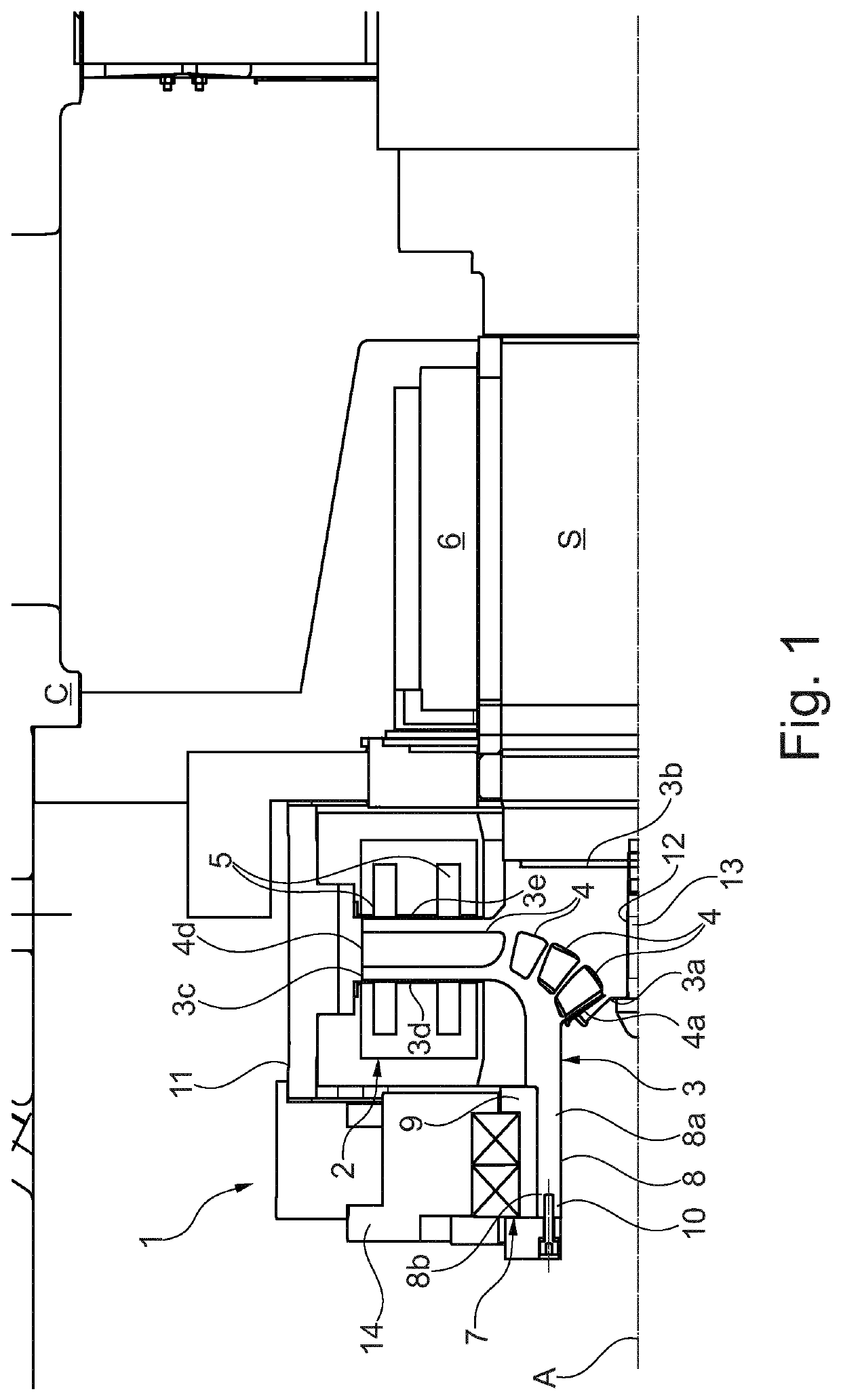
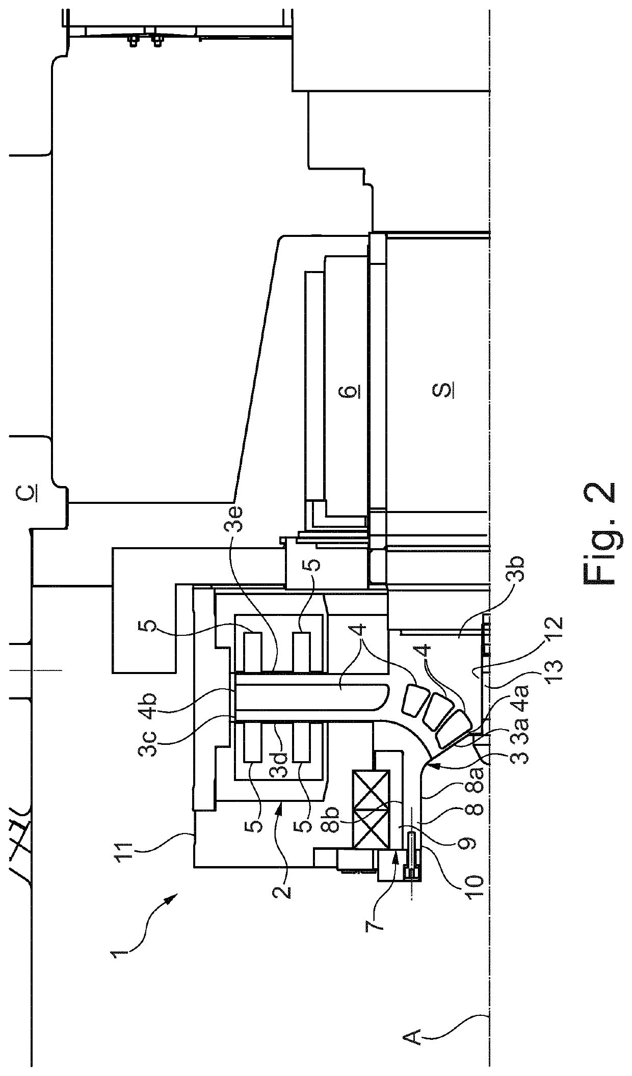
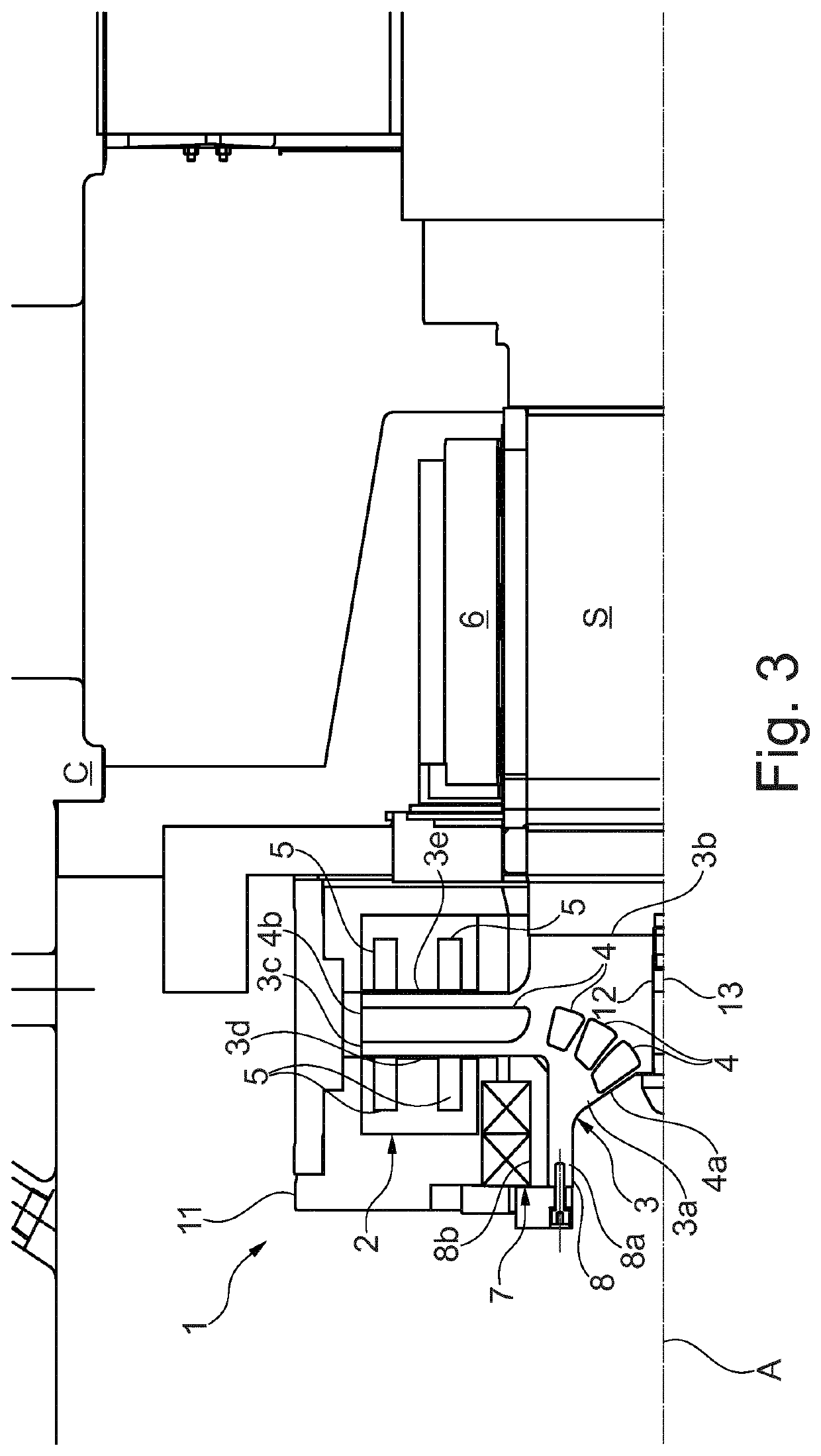
A magnetic bearing for a turbomachine includes a stator fixable to a structure of a turbomachine; a rotor magnetically coupled to the stator and defining a rotation axis, the rotor having a front central surface, a rear central surface opposite to the front central surface and an external surface with respect to the rotation axis; the rotor is provided with an internal channel configured to displace cooling fluid.

Description

BACKGROUND OF THE INVENTION[0001]The present disclosure relates to a magnetic bearing for a turbomachine. In the following disclosure a specific application of such bearing will be discussed in detail, namely a shaft of a motorcompressor. However, no loss of generality will be intended, since the same principles apply equally in similar applications.[0002]Generally a motorcompressor unit comprises a centrifugal compressor processing a process gas. The compressor is arranged in a housing together with a motor, usually consisting of an electric motor. The compressor generates a flow of compressed process gas.[0003]With more detail, the motor drives the compressor via a shared rotating shaft supported on each end by magnetic bearings. The shaft connects the rotor of the electric motor and the rotor of the centrifugal compressor on which the impellers of the compressor are installed. The shaft usually does not project outside the casing(s). Motorcompressor units used in the production o...

Claims


Application Information

Patent Timeline
Patent Type & Authority Patents(United States)
IPC IPC(8): H02K7/09H02K1/32F04D29/048F16C37/00F16C32/04F04D29/058F04D29/056F04D29/58F04D1/00F04D7/02
CPCF04D29/048F04D29/058F04D29/0563F04D29/584F16C32/0442F16C37/005H02K1/32H02K7/09F04D1/00F04D7/02F16C2360/24
Inventor DOZZINI, MATTEOBIGI, MANUELEFIORAVANTI, DUCCIOORTIZ NERI, MASSIMILIANO
Owner NUOVO PIGNONE TECH SRL
Learn More