Chain guide and chain drive apparatus

a chain drive and guide technology, applied in mechanical equipment, bearings, bearings, etc., can solve the problems of large transmission loss of torque, and achieve the effect of reducing the operating noise of the chain, less likely to fluctuate, and less likely to vibra

Inactive Publication Date: 2017-02-07
NTN CORP
View PDF83 Cites 0 Cited by
  • Summary
  • Abstract
  • Description
  • Claims
  • Application Information

AI Technical Summary

Benefits of technology

[0024]According to the chain guide offered by the present invention the outer circumferential surface of the roller has a cylindricity not higher than 20 μm, and therefore the contact pressure between the chain and the rollers is less likely to fluctuate when the rollers make contact with the chain while rotating at high speeds. Therefore, the chain is less likely to vibrate, i.e., the chain guide is capable of efficiently reducing the operating noise of the chain, and is superior in silence.

Problems solved by technology

A problem with this type of chain guides is a large transmission loss of torque due to a large tracking resistance of the chain since the contact with the chain is sliding contact.

Method used


Image

  • Chain guide and chain drive apparatus
  • Chain guide and chain drive apparatus
  • Chain guide and chain drive apparatus

Examples


Embodiment Construction

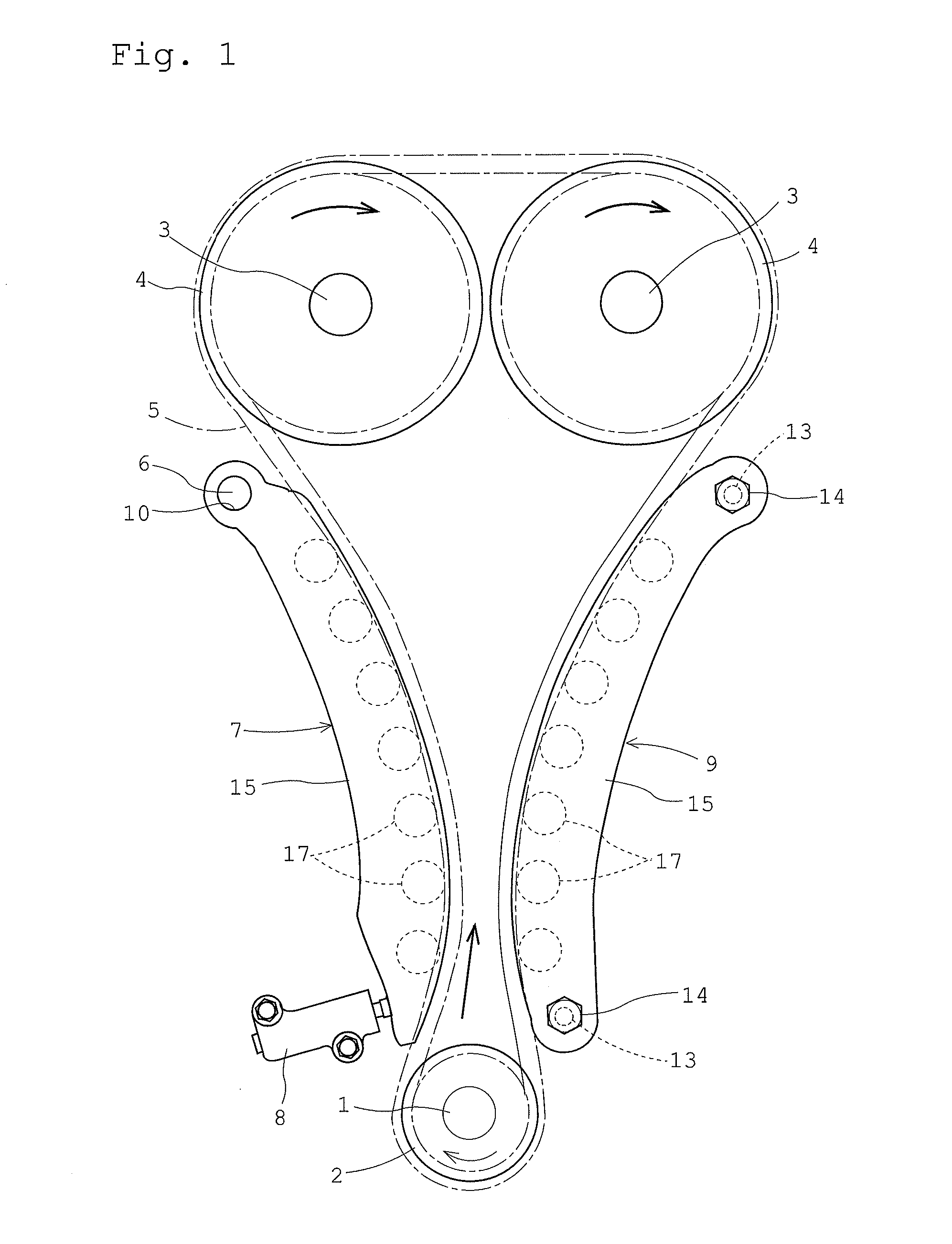
[0034]FIG. 1 shows a chain drive apparatus which includes chain guides according to an embodiment of the present invention. This chain drive apparatus includes: a drive sprocket 2 which is fixedly attached to a crankshaft 1 of an engine; a driven sprocket 4 which is fixedly attached to a cam shaft 3; and a chain 5 which is wound around the drive sprocket 2 and the driven sprocket 4. The chain 5 which transmits rotation of the crankshaft 1 to the cam shaft 3, so that valves (not illustrated) in combustion chambers are opened / closed as the cam shaft 3 rotates.

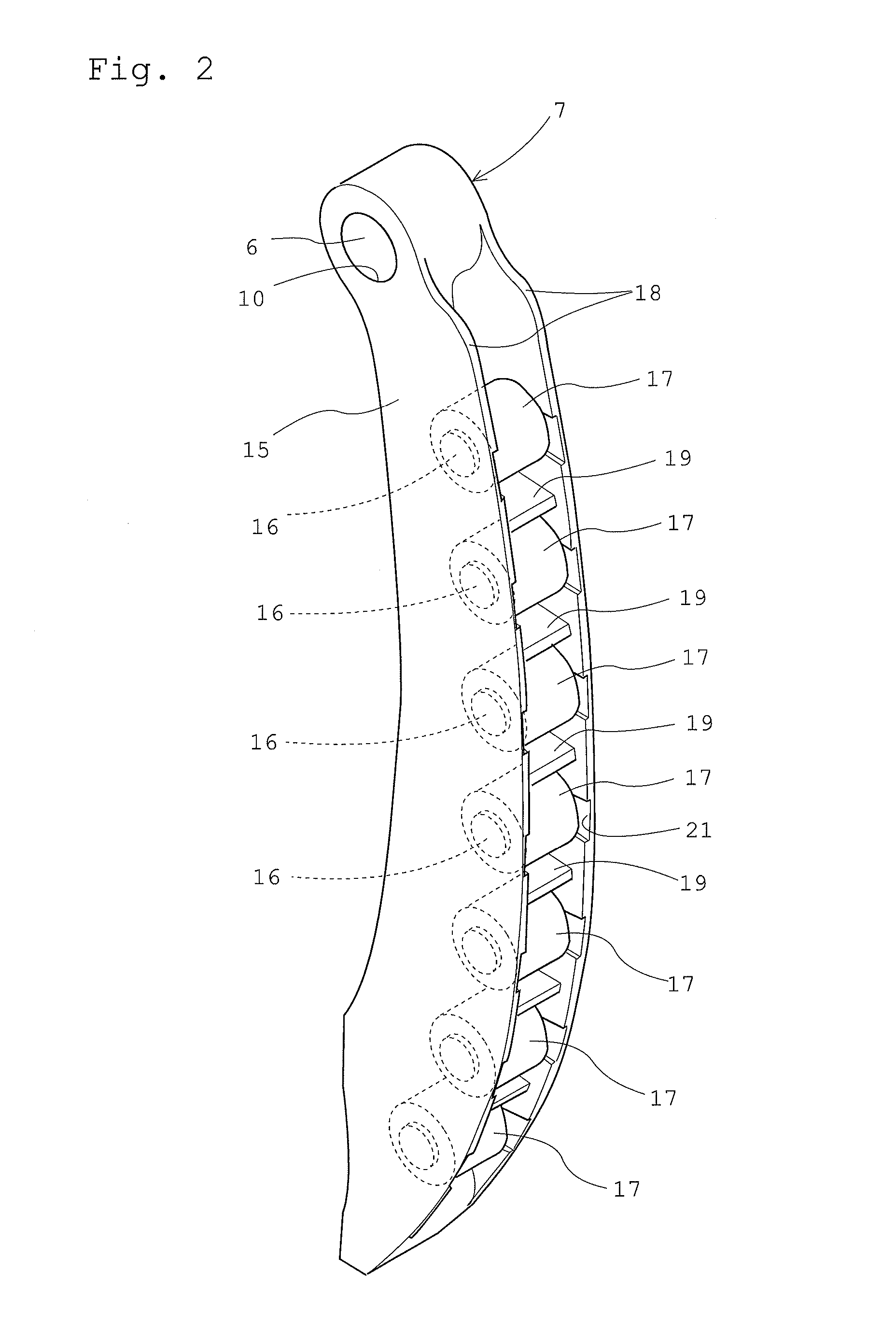
[0035]When the engine is operating, the crankshaft 1 makes rotation in a predetermined direction (clockwise in the figure). The chain 5, which is driven as the crankshaft 1 rotates, has a tension side or the side pulled by the drive sprocket 2, and a slack side or the side leaving the drive sprocket 2. On the slack side of the chain 5, there are provided a chain guide 7 which is supported pivotably around a pivot shaft 6; and a c...


PUM


Abstract

An object of the present invention is to provide a chain guide superior in silence, which includes: a guide base extending in a traveling direction of a chain; a plurality of roller shafts attached to the guide base at an interval along the traveling direction of the chain; and rollers each rotatably supported by one of the roller shafts. The roller has a cylindrical outer circumferential surface for guiding the chain. The outer circumferential surface of the roller has a cylindricity not greater than 20 μm.

Description

TECHNICAL FIELD[0001]The present invention relates to a chain guide for guiding a torque transmission chain, and to a chain drive apparatus including the chain guide.BACKGROUND ART[0002]In automotive engines, crankshaft rotation is transmitted to a cam shaft via a timing chain (hereinafter simply called chain), and valves in combustion chambers are opened / closed as the cam shaft rotates.[0003]Often, driving of the cam shaft as described above is achieved by a transmission apparatus or chain drive apparatus, which includes a drive sprocket attached to a crankshaft; a driven sprocket attached to the cam shaft; a chain wound around the drive sprocket and the driven sprocket; and a pivotable chain guide disposed on a slack side of the chain; a chain tensioner which presses the chain guide toward the chain; and a fixed chain guide disposed on a tension side of the chain.[0004]In this arrangement, the pivoting chain guide presses the chain with the chain tensioner's urging force, thereby ...

Claims


Application Information

Patent Timeline
Patent Type & Authority Patents(United States)
IPC IPC(8): F16H7/08F16C33/58F16H7/12F16H7/20F16C13/00F16H7/18F16C19/46
CPCF16H7/20F16C13/006F16C33/588F16H7/18F16C19/466F16C2240/40F16C2240/56F16C2240/60F16C2361/63F16H7/1281F16H2007/0865F16H2007/0893
Inventor OISHI, SHINJIKATO, AKIOYAMASHITA, TAKAHIROABE, KATSUFUMI
Owner NTN CORP
Why Eureka
Try Eureka