Apparatuses, systems, mobile gasification systems, and methods for gasifying residual biomass

a technology of residual biomass and gasification system, which is applied in the direction of gas dust removal, combustible gas purification/modification, combustible gas production, etc., can solve the problems of increasing energy costs, few advancements in technology, and agricultural industries that have been some of the hardest hit, so as to save power and tillage costs for farmers, and minimal maintenance requirements

Active Publication Date: 2017-02-14
AG ENERGY SOLUTIONS
View PDF59 Cites 1 Cited by
  • Summary
  • Abstract
  • Description
  • Claims
  • Application Information

AI Technical Summary

Benefits of technology

[0006]An example agricultural system that uses biomass gasification is disclosed herein. Disclosed systems and methods of operation utilize various improved gasification technologies to address the increase in costs and other problems associated with energy distribution. For example, a system may incorporate a mobile gasification system that is capable of using waste field residue to produce various valuable commodities, such as syngas, biochar, and / or electrical energy, thus providing an economically advantageous solution to the problems of existing power plants and farmers' field residue. The mobile attribute of the mobile gasification system may readily lend it to being placed in a farmer's field for convenient access to various farming systems (e.g. irrigation systems) and to the field residue itself. Thus, in some examples, electrical power can be provided for use throughout the growing and harvest seasons and the problems associated with traditional biomass plants, which require the transportation of the biomass to an offsite plant, are eliminated. During the off-season, the mobile attribute of may allow the mobile gasification system to be utilized to feed power into the homestead or to other systems thereby bypassing or surplussing an electrical grid, which may be susceptible to the impacts of storms and / or other attacks incidental or accidental. In one embodiment, the mobile gasification system may be configured to convert farm waste into electrical energy that is used to drive an irrigation system. An exemplary configuration, utilizes a mobile gasification system that is sized specifically to the available biomass and power demands of a specific field. For example, the mobile gasification system may be sized to utilize the field residue from one crop to provide the requisite power for irrigation of the next crop, while providing a balance between retained biomass for soil health and biomass for power generation. Thus, the mobile gasification system may save the farmer both power and tillage costs with minimal requirements for maintenance, while providing the advantages of baling and stacking the residue from their field in proximity to the power generation system.
[0007]Other advantages of the mobile gasification system exist, as well. For example, the mobile gasification system may be configured to store all or a portion of the generated syngas. The stored syngas may be used in place of natural gas or propane that is ordinarily piped into a home or commercial boiler, furnace, and / or range without significant changes to those systems. In an example, the mobile gasification system may have a modular configuration that allows for installation and removal of a syngas storage tank that can be used to transport stored syngas from the mobile gasification system, for example, back at the homestead, for connections to systems there, rather than moving the entire mobile gasification system. Another advantage offered by the mobile gasification system, is that multiple mobile gasification systems can be used in parallel to provide syngas, electricity, heat or combinations of these and the other outputs, etc. For example, two or more mobile gasification systems may be coupled such that their electrical outputs both feed a common irrigation system, or other system, in parallel. Likewise, two or more mobile gasification systems may output syngas into a common storage tank, such as one that might serve syngas to the homestead.
[0009]A gasifier disclosed herein may use several mechanisms, including a preheater that is capable of using hot syngas to preheat combustion air and incoming feedstock. Another mechanism of the gasifier disclosed herein is a stirring mechanism that may serve to prevent or reduce char and clinker buildup within the gasifier, as compared with gasifiers that incorporate filter screens at the outlet of the gasifier to trap char, ash, and other byproducts. These screens are highly prone to clogging and the silica present at the high levels in field straw quickly accumulates and glassifies at the temperatures present inside the gasifier. Not only does glassification of silica further clog the filter screen, but also it can quickly render the entire gasifier inoperable. The stirring mechanism may sweeps accumulations of biochar and other materials out of the syngas path, rather than filtering the biochar and other materials, and passes the syngas through a cyclone to separate out any entrained ashes. This stirring mechanism approach not only facilitates gasification of field straw, but may achieve a controllable gasification rate by utilizing the stirring mechanism to agitate the feedstock being gasified.

Problems solved by technology

However, few advancements in the technology have been realized over the years because of the availability and widespread adoption of fossil fuels.
The problem of rising energy costs is only exacerbated by an aging electrical distribution infrastructure.
Agricultural industries have been some of the hardest hit by these increased energy costs because agricultural margins tend to be lower than in other industries and because the industry itself is tightly regulated.
Meanwhile, advancements in agronomy have led to increased costs for the management of field residue.
The costs associated with breaking down biomass waste have increased as field production rates have increased.
These screens are highly prone to clogging and the silica present at the high levels in field straw quickly accumulates and glassifies at the temperatures present inside the gasifier.
Not only does glassification of silica further clog the filter screen, but also it can quickly render the entire gasifier inoperable.

Method used


Image

  • Apparatuses, systems, mobile gasification systems, and methods for gasifying residual biomass
  • Apparatuses, systems, mobile gasification systems, and methods for gasifying residual biomass
  • Apparatuses, systems, mobile gasification systems, and methods for gasifying residual biomass

Examples


Embodiment Construction

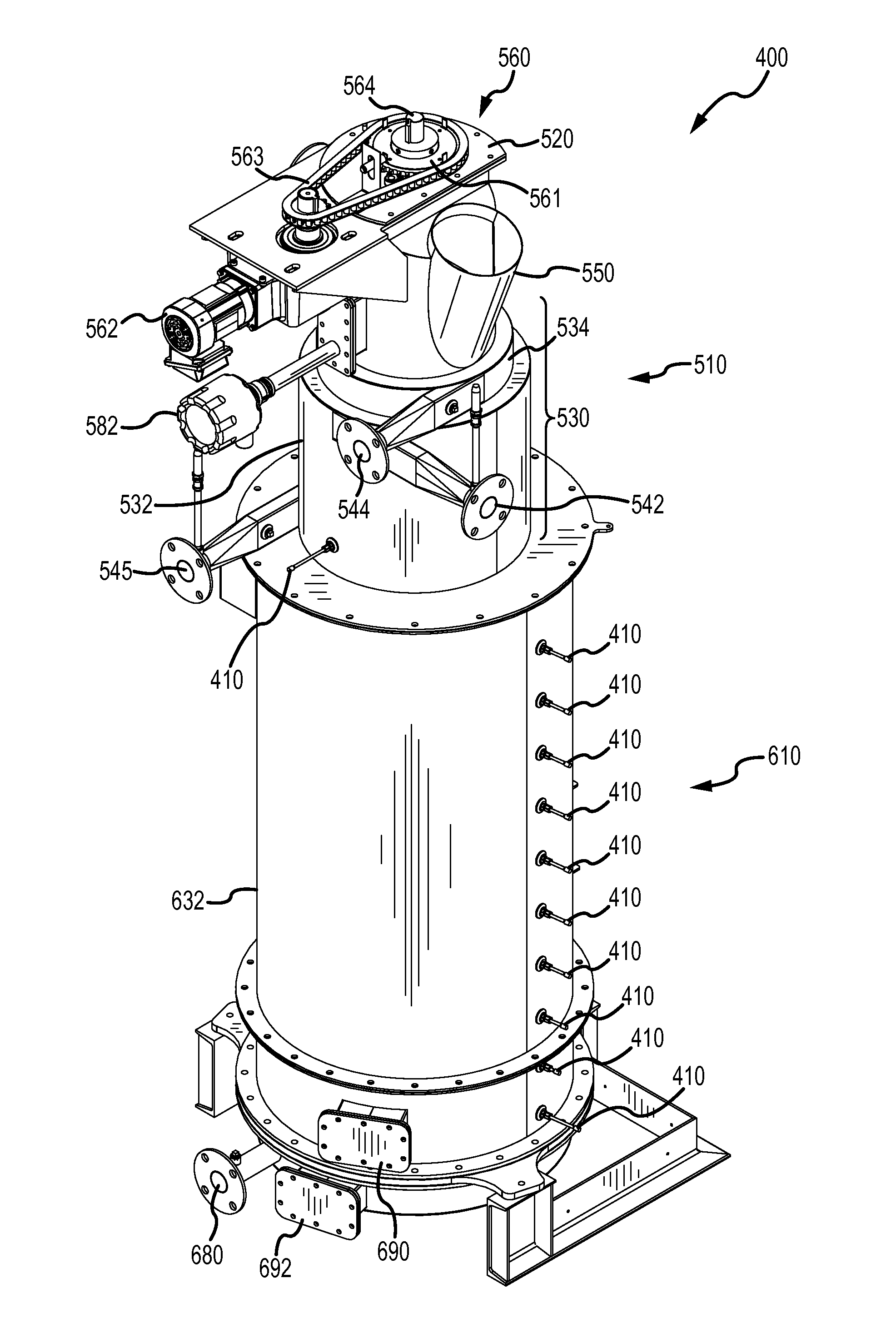
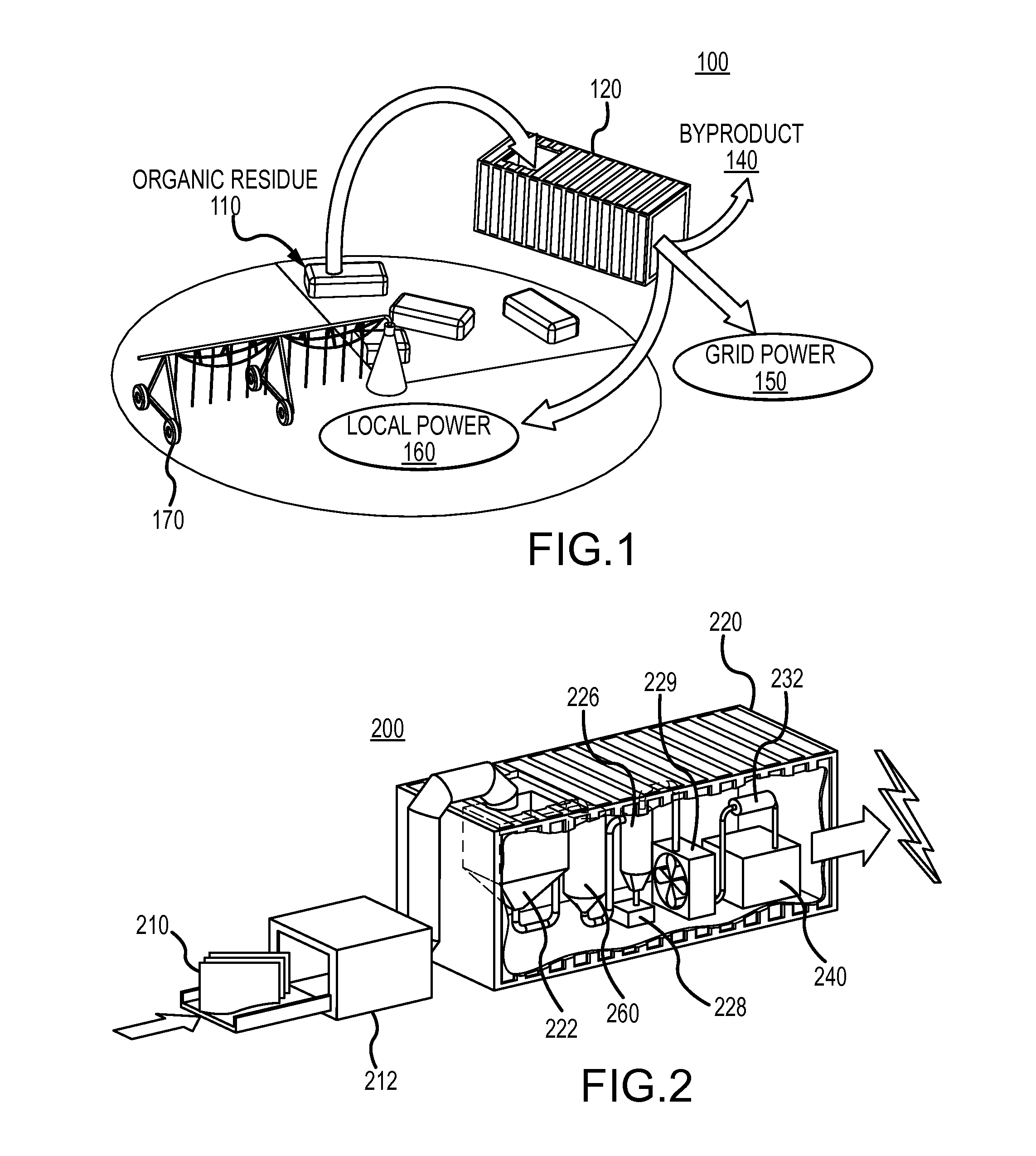
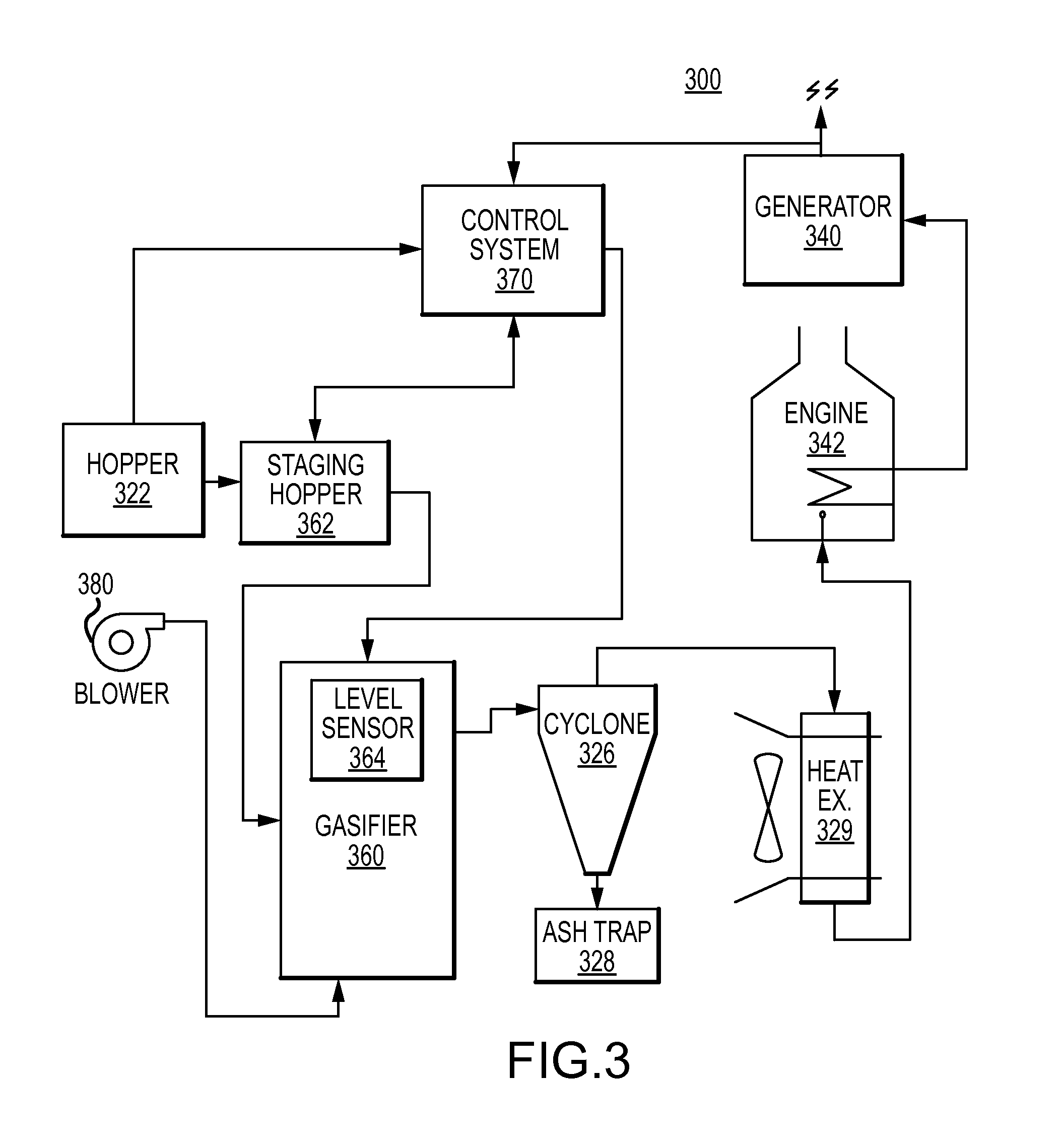
[0028]The present disclosure is generally directed to a mobile gasification system that may be used to fulfill the needs for sustainable energy solutions across the wide breadth of the agricultural industry. The mobile gasification system may use organic matter, such as residual biomass from a farming operation, to produce power for use in agricultural applications and / or for sales to the grid. While farming operations are the primary focus of this disclosure, other agricultural operations, such as logging, cultivation of algae, etc., are within the purview for use of the systems of this disclosure. Many of the specific details of certain embodiments of the disclosure are presented in the following description and in FIGS. 1-11, to provide a thorough understanding of such embodiments. One skilled in the art will understand, however, that the present disclosure may have additional embodiments, or that the present disclosure may be practiced without several of the details described in...


PUM

PropertyMeasurementUnit
angle of reposeaaaaaaaaaa
threshold temperatureaaaaaaaaaa
gas velocitiesaaaaaaaaaa

Abstract

Apparatuses, systems, mobile gasification systems, and methods for gasifying residual biomass are described. An example system may include a mobile gasification system configured to gasify feedstock generated from residual biomass to provide syngas. The mobile gasification system may be configured to generate electrical power using the syngas. The mobile gasification system may be configured to be installed in a transportable structure.

Description

CROSS REFERENCE TO RELATED APPLICATIONS[0001]We hereby claim benefit under Title 35, United States Code, Section 119(e) of U.S. provisional patent application Ser. Nos. 61 / 874,233 filed Sep. 5, 2013 and 61 / 877,824 filed Sep. 13, 2013. The 61 / 874,233 and 61 / 877,824 applications are hereby incorporated by reference into this application.TECHNICAL FIELD[0002]Embodiments described relate to gasification systems, and to mobile gasification systems using residual biomass, in particular.BACKGROUND OF THE DISCLOSURE[0003]Any discussion of the related art throughout the specification should in no way be considered as an admission that such related art is widely known or forms part of common general knowledge in the field.[0004]The process of producing energy using gasification has been in use since the 1800s. However, few advancements in the technology have been realized over the years because of the availability and widespread adoption of fossil fuels. In recent years, alternative sources t...

Claims


Application Information

Patent Timeline
Patent Type & Authority Patents(United States)
IPC IPC(8): B01J7/00C10J3/72C10J3/32C10K1/02
CPCC10J3/723C10J3/32C10J2200/156C10J2200/31C10J2300/0916C10J2300/0956C10J2300/165C10J2300/1869C10J2300/1884C10K1/026Y02P20/145C10J3/74
Inventor APPEL, PHILIP W.WEIR, THOMAS D.CULLEY, JACOB M.FARLEY, TIMOTHY E.HOWARD, DANIEL A.LOVE, SARAH E.
Owner AG ENERGY SOLUTIONS
Why Eureka
Try Eureka