Pressure compensation system

a pressure compensation and system technology, applied in fluid pressure control, electrical apparatus casings/cabinets/drawers, boreholes/well accessories, etc., can solve the problems of only a small increase in the safety and reliability of pressure compensators, difficult construction of such subsea enclosures, and high cost, so as to reduce the utilization of each pressure compensator, reduce the likelihood of both bellows failing within a short period of time, and effectively double the life of pressure compensation systems

Active Publication Date: 2017-02-14
SIEMENS ENERGY AS
View PDF48 Cites 3 Cited by
  • Summary
  • Abstract
  • Description
  • Claims
  • Application Information

AI Technical Summary

Benefits of technology

[0012]There is a need for providing improved pressure compensation for a subsea device. In particular, there is a need to achieve pressure compensation with improved reliability.
[0046]In some embodiments, the further pressure compensators may include at least a second and a third pressure compensator. If it is determined that one of the further pressure compensators has failed, the method may further include bringing the pressure compensation into a state in which a flow connection between the second pressure compensator and the third pressure compensator is closed, detecting the displacement of at least the second or the third pressure compensator and, based on the detected displacement, determining whether the second or the third pressure compensator has failed. Accordingly, also with more than two pressure compensators, it may be detected fast and efficiently which of the pressure compensators that has failed. More than three pressure compensators may be provided, and that the method may be applied correspondingly.

Problems solved by technology

The construction of such subsea enclosures is technically challenging.
Such enclosures need to have relatively thick walls and are thus bulky and heavy, since they have to withstand high differential pressures.
Temperature changes may be caused by deployment at the subsea location and by internal heating, e.g., due to electric losses.
Such type of double barrier may increase the safety and reliability of the pressure compensator only insignificantly.
A failure of the pressure compensator may be caused by fatigue of the material of the bellows part, e.g., by the formation of cracks and thus leaks in the bellows part of the pressure compensator.
Even so, both bellows parts undergo the same compression / decompression cycles, and are accordingly experiencing the same stress and fatigue.
Both bellows portions are thus likely to fail within a relatively short period of time.

Method used


Image

  • Pressure compensation system
  • Pressure compensation system
  • Pressure compensation system

Examples


Embodiment Construction

[0055]In the following, the embodiments illustrated in the accompanying drawings are described in more detail. The following description is only illustrative and non-restrictive. The drawings are only schematic representations, and elements in the drawings are not necessarily to scale with each other.

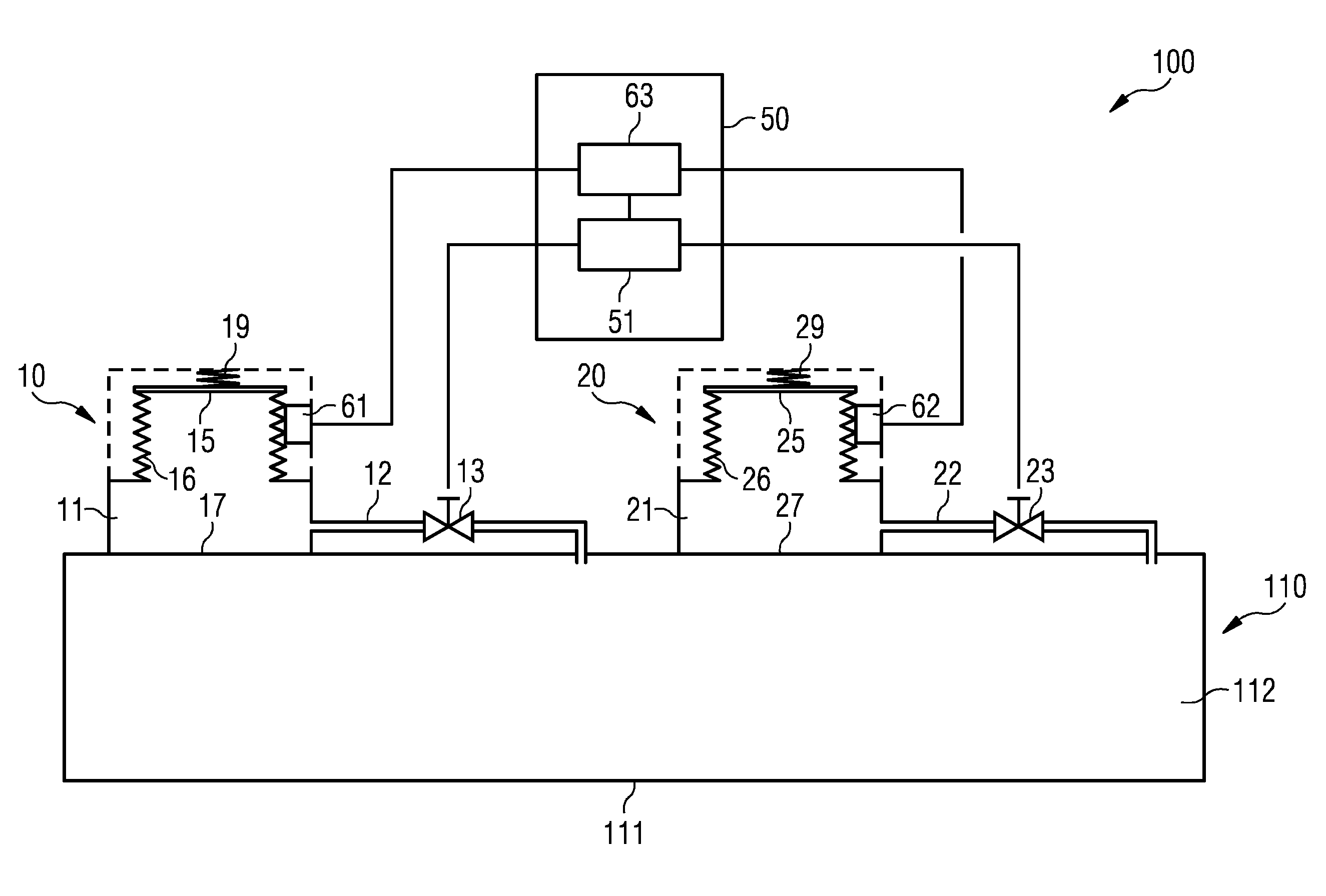
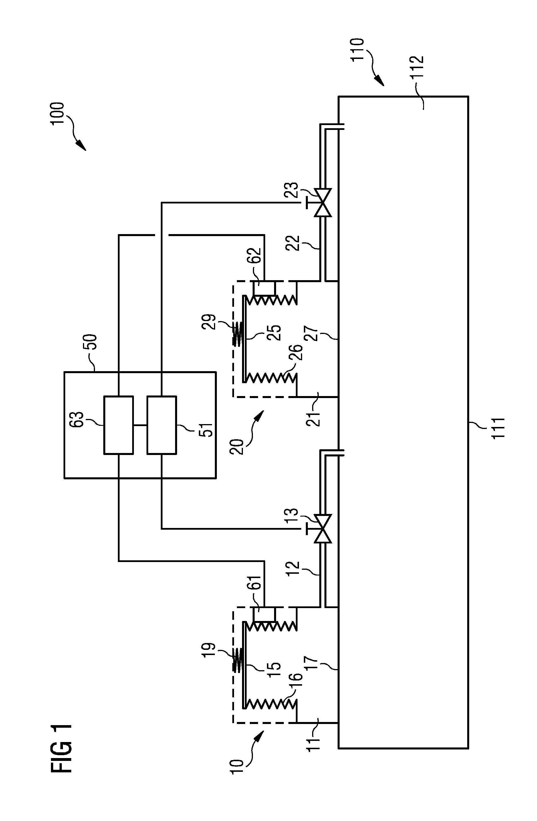
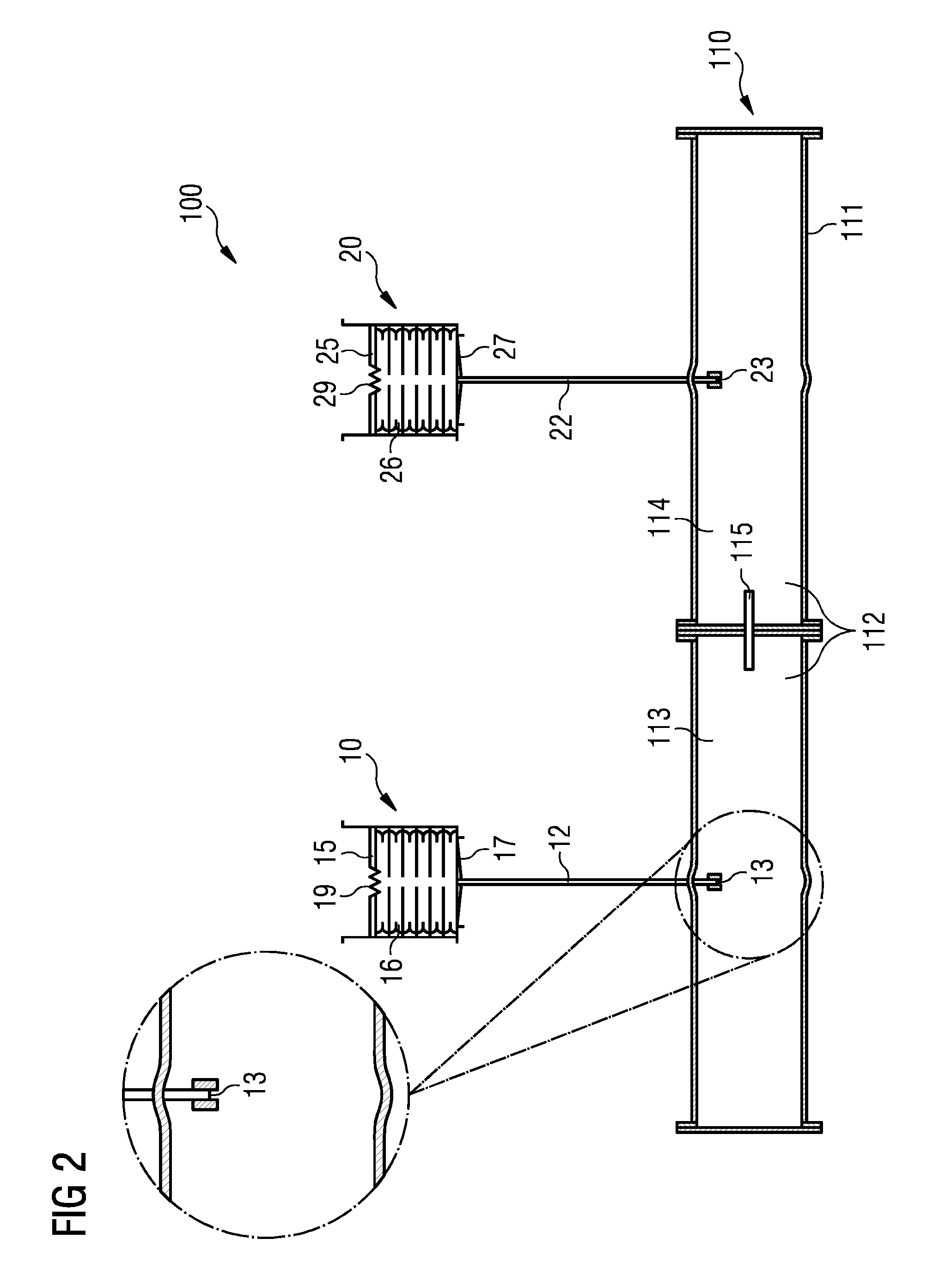
[0056]FIG. 1 depicts a subsea device 110 having a subsea enclosure 111 that forms a chamber 112. The chamber 112 is filled with a liquid, in particular, a dielectric liquid, such as transformer oil, silicon oil, or the like. A pressure compensation system 100 is provided for compensating volume variations of the liquid filling chamber 112. As an example, the temperature of the liquid may change when the subsea device 110 is installed at the subsea location. The temperature may, for example, change from about 20° C. to about 4° C., which may lead to a significant volume change. Furthermore, in operation, electric or electronic components disposed in the subsea enclosure 111 may generate ...


PUM

PropertyMeasurementUnit
pressuresaaaaaaaaaa
internal pressureaaaaaaaaaa

Abstract

A pressure compensation system is provided. A subsea enclosure of the subsea device encloses the chamber. A first pressure compensator has a first compensation volume and provides pressure balancing between ambient medium surrounding the subsea device and the first compensation volume. A first biasing device is configured to bias the first pressure compensator such that the pressure in the first compensation volume is higher than the pressure in the ambient medium surrounding the subsea device. A second pressure compensator has a second compensation volume and provides pressure balancing between the ambient medium and the second compensation volume. A second biasing device biases the second pressure compensator such that the pressure in the second compensation volume is higher than the pressure in the ambient medium. A control unit is connected to control first and second valves arranged in flow connections between the first and second compensation volumes and the chamber.

Description

CROSS-REFERENCE TO RELATED APPLICATIONS[0001]This application claims the benefit of EP 14162433.8, filed on Mar. 28, 2014, which is hereby incorporated by reference in its entirety.TECHNICAL FIELD[0002]The present embodiments relate to a pressure compensation system for compensating volume variations of a liquid in a chamber of a subsea device and to a method of operating a pressure compensation system.BACKGROUND[0003]Due to the increasing energy demand, offshore oil and gas production is moving into deeper waters. For providing an efficient and secure production of hydrocarbons from a subsea well, processing facilities are being installed at the ocean floor. Such subsea installations may include a range of components, including pumps, compressors, and the like as well as a power grid for providing such components with electric power. The power grid may, for example, include a subsea transformer, subsea switchgear, and subsea variable speed drives (VSDs). Such components of a subsea...

Claims


Application Information

Patent Timeline
Patent Type & Authority Patents(United States)
IPC IPC(8): H01F27/14G05D16/20E21B33/035E21B33/038H05K5/06
CPCH01F27/14E21B33/035E21B33/0385G05D16/2093H05K5/068F15B2201/205F15B2201/3153F15B2201/515Y10T137/0379Y10T137/2036
Inventor KRISTENSEN, KNUT SCHONHOWD
Owner SIEMENS ENERGY AS
Why Eureka
Try Eureka