Wiring unit for automatic transmission

a technology for wiring units and automatic transmissions, applied in the direction of printed circuit aspects, transportation and packaging, printed circuit non-printed electric components association, etc., can solve the problem of increasing the number of components, and achieve satisfactory swaged state and reduce the number of components

Active Publication Date: 2017-02-21
SUMITOMO WIRING SYST LTD
View PDF13 Cites 0 Cited by
  • Summary
  • Abstract
  • Description
  • Claims
  • Application Information

AI Technical Summary

Benefits of technology

[0009]According to the wiring unit for automatic transmission of the present invention, the electrical component is fixed by swaging the swaging piece integrally formed to the holding portion. Thus, unlike before, a dedicated component for fixing the electrical component is not necessary and the number of components can be reduced.
[0010]Further, since the positioning protrusion projects on one of the electrical component and the holding portion and the other is formed with the receiving portion into which the positioning protrusion is fitted to position the electrical component, the electrical component can be positioned on the holding plate by fitting the positioning protrusion and the receiving portion prior to a swaging operation. In this way, the burden of holding the electrical component during the swaging operation is released and a satisfactory swaged state is obtained.
[0011]Further, since the positioning protrusion or the receiving portion is arranged near the holding plate, a situation of erroneous assembling where the electrical component is erroneously assembled in an inverted manner can be avoided.

Problems solved by technology

However, if such a fixing method is adopted, a dedicated component called the holder 102 is necessary to mount the ROM 101, thereby presenting a problem of increasing the number of components.

Method used


Image

  • Wiring unit for automatic transmission
  • Wiring unit for automatic transmission
  • Wiring unit for automatic transmission

Examples


Embodiment Construction

[0025]Preferred embodiments of the present invention are described.

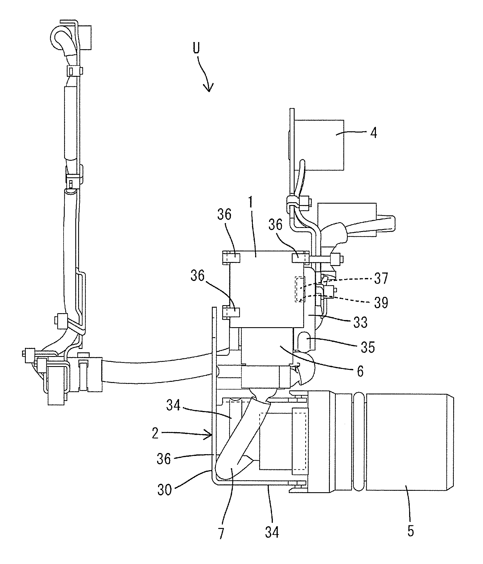
[0026]In the wiring unit for automatic transmission of the present invention, each swaging piece may be formed of a base portion standing from the holding portion and a swaging portion formed to be somewhat narrow at a tip side of the base portion and swageable to the electrical component.

[0027]Since the narrow swaging portion is formed on the tip of the base portion of each swaging piece in this way, swaging can be performed with a relatively light operation force while the electrical component is sandwiched.

[0028]Furthermore, the holding plate may include a free end part arranged via a bent portion, the holding portion may be formed on the free end part and the bent portion may be formed with a reinforcing rib in an area straddling the bent portion.

[0029]According to such a configuration, a bending force acts on the holding portion with the bent portion as a center if the swaging piece is swaged to the electrical c...


PUM


Abstract

A wiring unit (U) for automatic transmission mounted in an automatic transmission of an automotive vehicle and configured to execute a control relating to a speed changing operation includes a wiring harness (WH), a ROM (1) connected to the wiring harness and a holding plate (2) made of metal for holding these. The holding plate (2) is formed with a holding portion (33) on which the ROM (1) is to be placed, and the holding portion (33) is integrally formed with a plurality of swaging pieces (36) for fixing the ROM (1) on the holding portion (33) by being swaged to the ROM (1). Further, the ROM (1) is formed with a positioning protrusion (37), and the holding portion (33) is formed with a receiving hole (39) into which the positioning protrusion (37) is aligned and fitted.

Description

BACKGROUND[0001]1. Field of the Invention[0002]The present invention relates to a wiring unit for automatic transmission.[0003]2. Description of the Related Art[0004]Conventionally, electrical components such as control components (ROM, etc.) and various sensors and a wiring unit formed by unitizing electrical wiring for signal transmission among these electrical components or external signal transmission are assembled, for example, into an automatic transmission of an automotive vehicle to control a speed changing operation. A wiring unit having such a configuration is known from Japanese Unexamined Patent Publication No. 2010-106946.[0005]Aside from the above one, a wiring unit may be so configured that electrical components and a wiring harness are assembled on a holding plate made of metal. In such a case, a ROM 101 may be held on a holding plate 100 as shown in FIG. 13. As shown in FIG. 13, the ROM 101 is fixed to the holding plate 100 via a holder 102. In fixing the ROM 101, t...

Claims


Application Information

Patent Timeline
Patent Type & Authority Patents(United States)
IPC IPC(8): B60R16/02H05K1/02B60R16/023H05K1/05H05K7/02H05K1/18
CPCB60R16/0231B60R16/0215H05K1/0296H05K1/05H05K1/181H05K7/02H05K2201/09009
Inventor KAWASHIMA, YUJISHIMAMURA, MITSUHIROITOU, SATORU
Owner SUMITOMO WIRING SYST LTD
Why Eureka
Try Eureka