Carton with corner crumple zones

Active Publication Date: 2017-02-21
GREEN BEI PACKAGING INC
View PDF31 Cites 8 Cited by
  • Summary
  • Abstract
  • Description
  • Claims
  • Application Information

AI Technical Summary

Benefits of technology

[0007]In one aspect, the present invention provides a shipping carton formed from a single blank or sheet of material, having a force receiving area located adjacent opposing edges of the carton's top and bottom edges. Each force receiving area is con

Problems solved by technology

However, the use of a clamping lift truck to lift and move appliance cartons can result in undesirable damage to the carton.
Typically this crease appears along the center of the carton and is visually unattractive.
In some instances, this crease extends inwardly and c

Method used


Image

  • Carton with corner crumple zones
  • Carton with corner crumple zones
  • Carton with corner crumple zones

Examples


embodiment one

I. Embodiment One

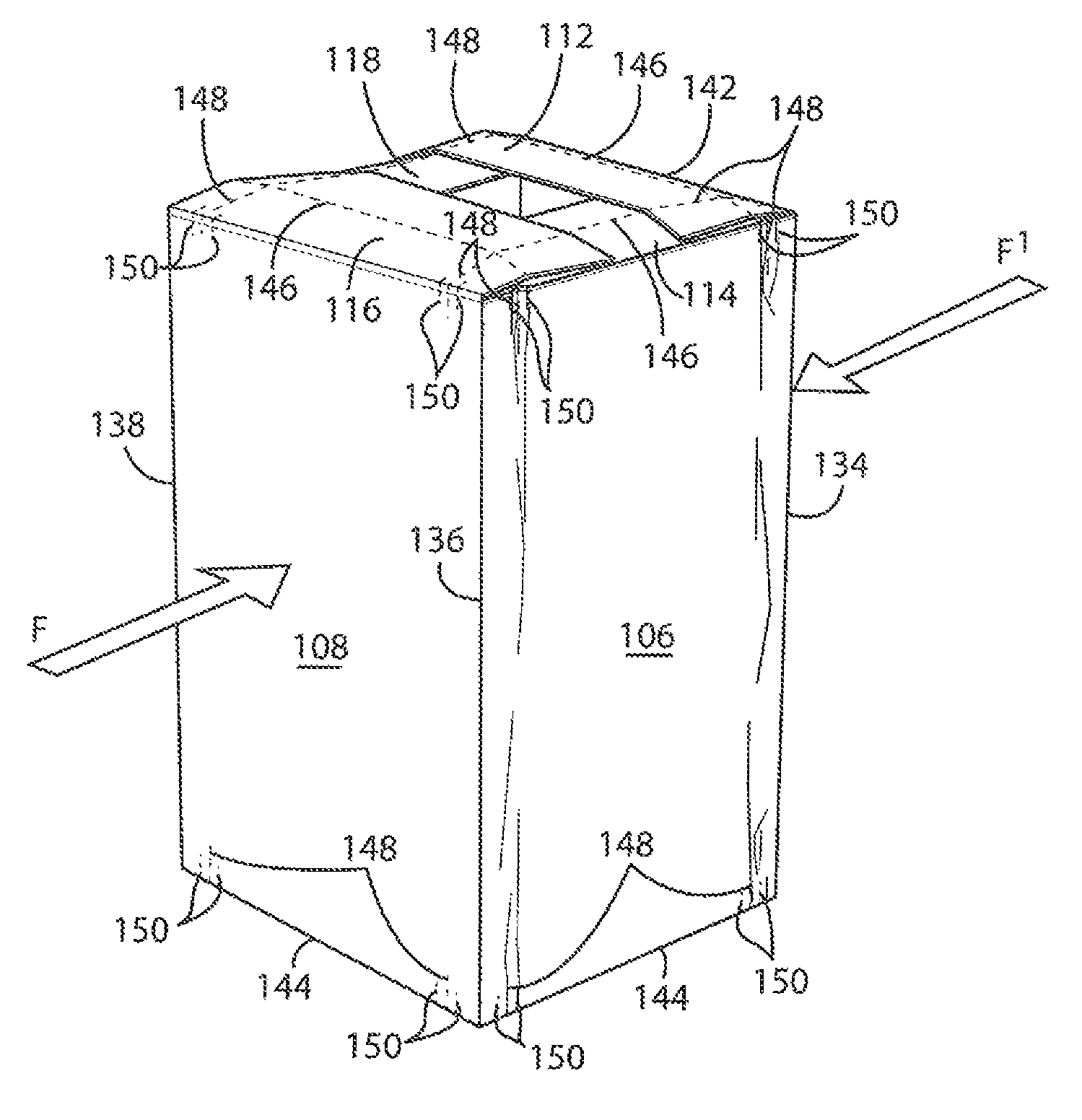
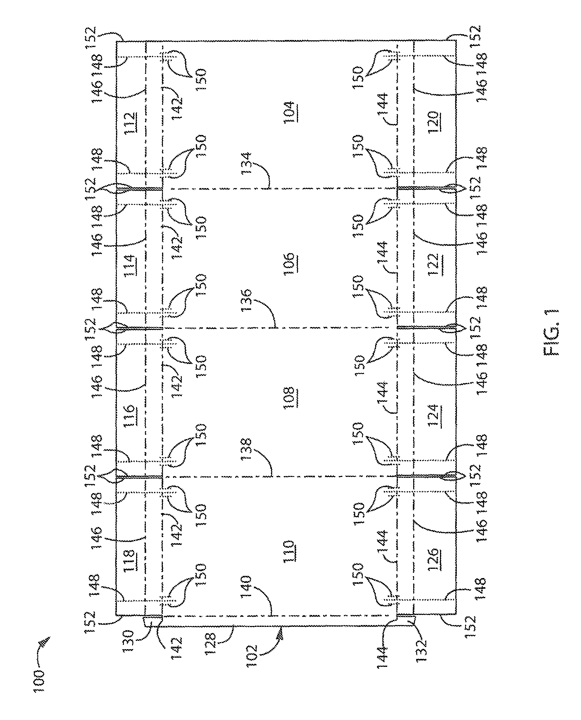
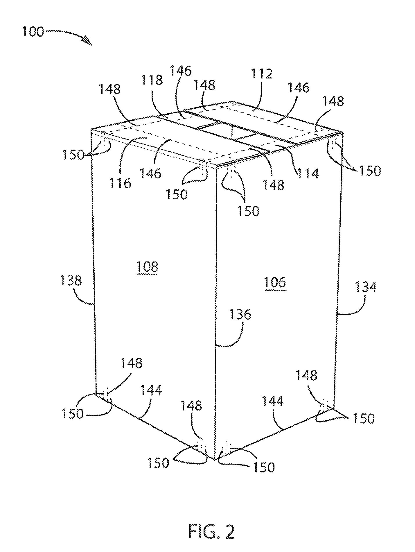
[0024]Referring initially to FIGS. 1-4 and particularly FIG. 1, there is shown a shipping carton 100 according to one embodiment of the present invention. The shipping carton 100 generally is made of a sheet or blank 102 of packaging material. The packaging material may consist of corrugated board or any similar material suitable for use in shipping container construction. In a manner as is known, the corrugated board consists of a fluted corrugated core located between two sheets of kraft paper or linerboard, in a manner as is known. In one embodiment the flutes of the inner core have a longitudinal axis that is parallel to the longitudinal axis of the folded and erected carton 100. The blank 102 may be stamped or cut from a sheet of the packaging material while in a substantially flat orientation, and subsequently folded to form the carton 100. The outer surface of the carton 100 may be printed to display information such as contents details, shipping information,...

embodiment two

II. Embodiment Two

[0033]Turning now to FIGS. 5-9 and initially FIG. 5, there is shown a shipping carton 200 according to a second embodiment of the present invention. The shipping carton 200 generally is made of a sheet or blank 202 of packaging material. The packaging material may consist of corrugated board or any similar material suitable for use in shipping container construction. In a manner as is known, the corrugated board consists of a fluted corrugated core located between two sheets of kraft paper or linerboard, in a manner as is known. In one embodiment the flutes of the inner core have a longitudinal axis that is parallel to the longitudinal axis of the folded and erected carton 200. The blank 202 may be stamped or cut from a sheet of the packaging material while in a substantially flat orientation, and subsequently folded to form the carton 200. The outer surface of the carton 200 may be printed to display information such as contents details, shipping information, remo...

embodiment three

Ill. Embodiment Three

[0042]Turning now to FIGS. 10 and 11 and initially FIG. 10, there is shown a shipping carton cap 300 according to another embodiment of the present invention. The shipping carton cap 300 generally is made of a sheet or blank 302 of packaging material. The packaging material may consist of corrugated board or any similar material suitable for use in shipping container construction. In a manner as is known, the corrugated board consists of a fluted corrugated core located between two sheets of kraft paper or linerboard, in a manner as is known. In one embodiment the flutes of the inner core have a longitudinal axis that is parallel to the longitudinal axis of the folded and erected carton cap 300. The blank 302 may be stamped or cut from a sheet of the packaging material while in a substantially flat orientation, and subsequently folded to form the carton cap 300. The outer surface of the carton cap 300 may be printed to display information such as contents detail...


PUM


Abstract

A shipping carton having a force receiving area located adjacent opposing edges of the carton's top and bottom edges. The force receiving area is configured to deform in the presence of an external force and distribute that force through the force receiving area while minimizing the transfer of force directly to the appliance and minimizing damage to the surface panels of the shipping carton.

Description

CROSS-REFERENCE TO RELATED APPLICATION[0001]This application claims the benefit of U.S. Ser. No. 61 / 827,882 filed May 28, 2013, the disclosure of which is incorporated herein in its entirety.FIELD. OF THE INVENTION[0002]The present invention relates to a shipping carton and, more particularly a shipping carton having integrated crumple zones for accepting lateral forces exerted on the carton during transportation.BACKGROUND OF THE INVENTION[0003]Large consumer appliances such as washing machines, dryers, dishwashers, ranges, freezers and refrigerators are typically packaged in individual cartons during their transportation from the manufacturer to the retailer, and ultimately to the end purchaser. The use of a carton is important in protecting the exterior of the appliance from potential damage, such as scratching and chipping the finish or even denting the appliance body. Conventional home appliance cartons are formed of one or more pieces of packaging material that form a six side...

Claims


Application Information

Patent Timeline
IPC IPC(8): B65D81/02B65D5/44B65D5/42B65D81/05B65D5/50B65D85/64B65D81/17
CPCB65D5/50B65D81/053B65D5/4266B65D5/445B65D85/64B65D5/42B65D81/054B65D85/68B65D2585/6815B65D2585/6817B65D2585/682B65D2585/6855
Inventor CAPOGROSSO, ANDREW M.
Owner GREEN BEI PACKAGING INC
Why Eureka
Try Eureka