Eureka AIR delivers breakthrough ideas for toughest innovation challenges, trusted by R&D personnel around the world.

System and method for improving canister purging

a technology of purging operation and canister, which is applied in the direction of combustion-air/fuel-air treatment, electrical control, separation processes, etc., can solve the problems of reduced purging efficiency, reduced purging flow through the ejector, and reduced so as to improve the purging operation and reduce the performance of the ejector in terms of purging the fuel vapor canister.

Active Publication Date: 2017-02-21
FORD GLOBAL TECH LLC
View PDF8 Cites 7 Cited by
  • Summary
  • Abstract
  • Description
  • Claims
  • Application Information

AI Technical Summary

Benefits of technology

[0002]Vehicle fuel systems include evaporative emission control systems designed to reduce the release of fuel vapors to the atmosphere. For example, vaporized hydrocarbons (HCs) from a fuel tank may be stored in a fuel vapor canister packed with an adsorbent which adsorbs and stores the vapors. At a later time, when the engine is in operation, the evaporative emission control system may allow the vapors to be purged into an engine intake manifold for use as fuel.
[0003]The purging of fuel vapors from the fuel vapor canister may involve opening a canister purge valve coupled to a conduit between the fuel vapor canister and the intake manifold. During a purge operation, vacuum or negative pressure in the intake manifold may draw air through the fuel vapor canister enabling desorption of fuel vapors from the canister. These desorbed fuel vapors may flow through the canister purge valve into the intake manifold. As such, the canister purge valve may regulate the flow of fuel vapors into the intake manifold via a sonic choke positioned in series with the canister purge valve. Accordingly, the sonic choke may function as a flow restrictor in the purge path between the valve and the intake manifold.
[0011]In this way, the amount of fuel vapors that may be purged from a fuel vapor canister during boosted conditions in a turbocharged engine may be increased. Further, the amount of fuel vapors that may be purged from a fuel vapor canister during shallow intake manifold vacuum levels may be increased. By coupling the ejector to the fuel vapor canister via two separate flow paths, one through a canister purge valve, and the other through a bypass valve, the canister purge valve may be circumvented and a purge flow rate to the compressor inlet may be enhanced during boosted conditions where manifold vacuum is lower. Further, by controlling compressor bypass flow and ejector vacuum via an ejector shut-off valve based on engine conditions, engine performance may be enhanced. Overall, vehicle fuel economy and emissions compliance may be improved.

Problems solved by technology

However, purge flow through the ejector may be lower because the sonic choke in the canister purge valve may excessively restrict canister purge flow to the suction port of the ejector.
Accordingly, a performance of the ejector in terms of purging the fuel vapor canister may be severely diminished by the presence of the sonic choke in the flow path.
As such, during lower boost levels, the purging efficiency may be reduced.
Accordingly, manifold vacuum during idle conditions may not be availed for canister purging.

Method used


Image

  • System and method for improving canister purging
  • System and method for improving canister purging
  • System and method for improving canister purging

Examples


Embodiment Construction

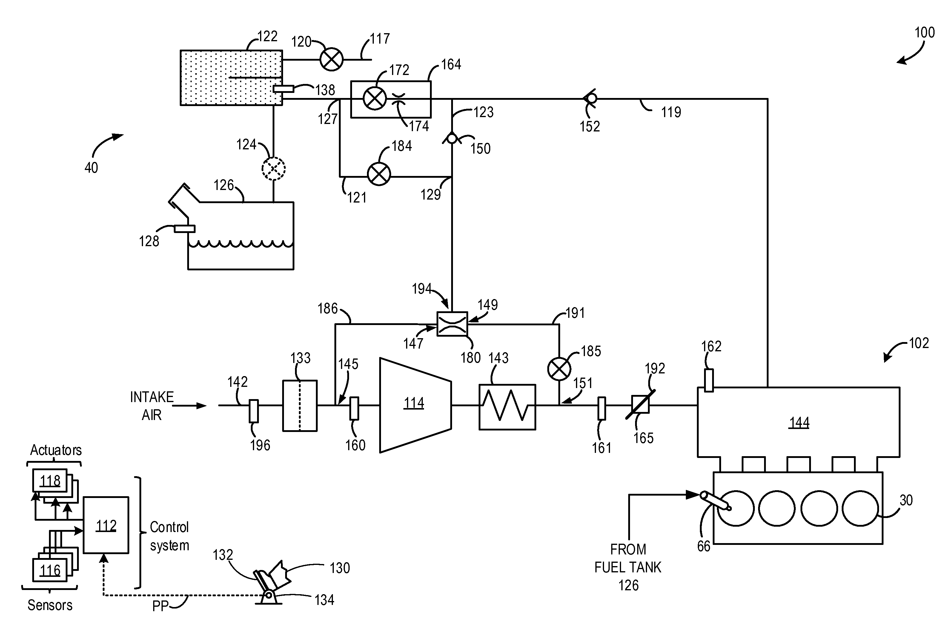
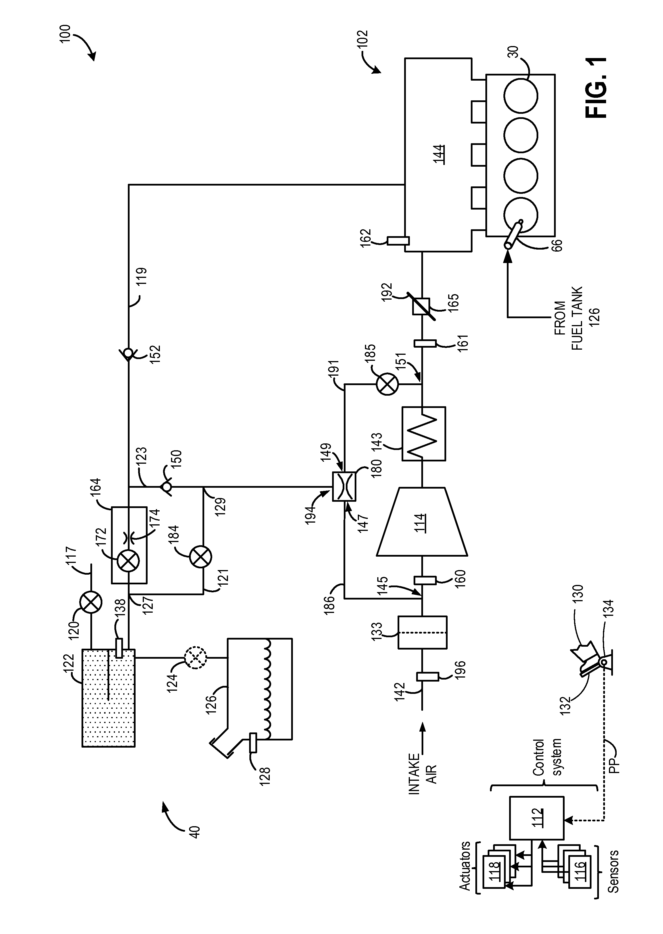
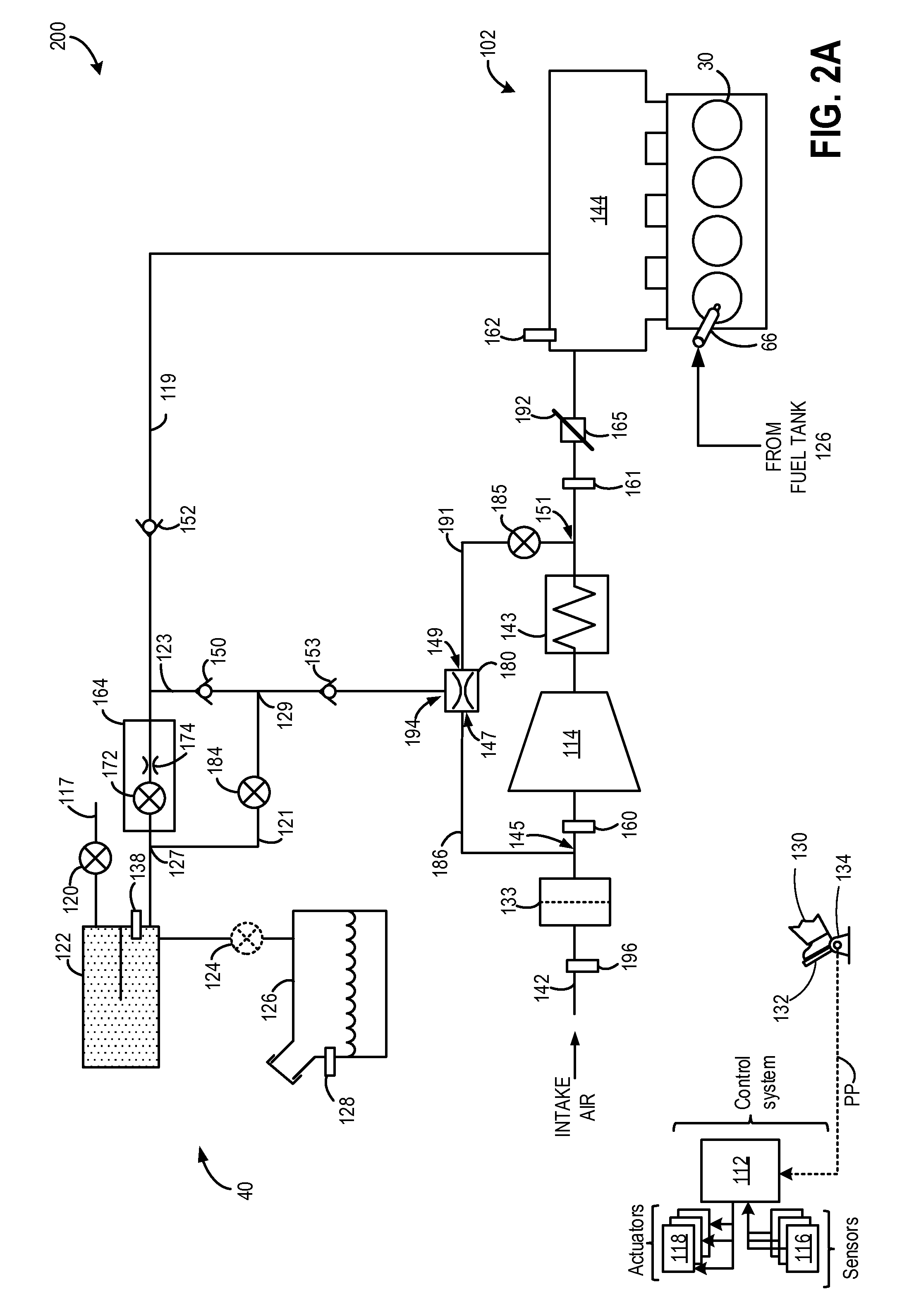
[0020]The following detailed description relates to systems and methods for improving purging of a fuel vapor canister included in an engine system, such as the engine system of FIGS. 1-2B. The engine system may be a boosted engine including a turbine and a compressor. The fuel vapor canister may be coupled to an engine intake via a canister purge valve, where the canister purge valve may include a solenoid valve and a sonic choke housed within a common container of the canister purge valve. Stored fuel vapors in the fuel vapor canister may be purged via two paths into an intake of the engine. During non-boosted conditions, fuel vapors may be purged via the solenoid valve and through the sonic choke of the canister purge valve into an intake manifold (FIG. 3). During boosted conditions, fuel vapors from the fuel vapor canister may be purged through an ejector coupled to a bypass passage around the compressor (FIGS. 3-4). Herein, the fuel vapors may be delivered to an inlet of the co...


PUM


Abstract

Systems and methods are provided for controlling a purging operation of a fuel vapor canister in a boosted engine. One method comprises purging stored fuel vapors from the fuel vapor canister to an inlet of the compressor via an ejector while bypassing a canister purge valve, the ejector being fluidically coupled to the fuel vapor canister by a distinct passage coupled upstream of the canister purge valve, where motive flow through the ejector may be regulated by a shut-off valve. The shut-off valve may be adjusted based on whether or not the engine is boosted.

Description

FIELD[0001]The present disclosure relates to systems and methods for improving purging of fuel vapors from a fuel vapor canister.BACKGROUND AND SUMMARY[0002]Vehicle fuel systems include evaporative emission control systems designed to reduce the release of fuel vapors to the atmosphere. For example, vaporized hydrocarbons (HCs) from a fuel tank may be stored in a fuel vapor canister packed with an adsorbent which adsorbs and stores the vapors. At a later time, when the engine is in operation, the evaporative emission control system may allow the vapors to be purged into an engine intake manifold for use as fuel.[0003]The purging of fuel vapors from the fuel vapor canister may involve opening a canister purge valve coupled to a conduit between the fuel vapor canister and the intake manifold. During a purge operation, vacuum or negative pressure in the intake manifold may draw air through the fuel vapor canister enabling desorption of fuel vapors from the canister. These desorbed fuel...

Claims


Application Information

Patent Timeline
Patent Type & Authority Patents(United States)
IPC IPC(8): F02D41/00F02B33/44F02D41/26F02M35/104F02M35/10F02M25/08
CPCF02D41/0032F02B33/44F02D41/26F02M25/0836F02M25/0854F02M25/0872F02M35/104F02M35/10222F02D41/003F02M25/08F02D41/0007F02D2200/0406F02M25/089Y02T10/12B01D53/0454F02D41/004B01D2257/7022B01D2259/4516
Inventor PURSIFULL, ROSS DYKSTRA
Owner FORD GLOBAL TECH LLC
Why Eureka
Eureka Blog
Learn More