
Sagittal saw

a sagittal saw and saw blade technology, applied in the direction of surgical saws, etc., can solve the problems of undesirable damage to bone cells, affecting the cutting rate of sagittal saws, and generating a significant amount of heat in the immediate vicinity, so as to increase the cutting rate, reduce the overall cutting time, and increase the cutting rate

Active Publication Date: 2017-02-28
TUFTS UNIV
View PDF6 Cites 2 Cited by
  • Summary
  • Abstract
  • Description
  • Claims
  • Application Information

AI Technical Summary

Benefits of technology

The device achieves higher cutting rates, reduces patient recovery time, and provides better control and efficiency by applying thrust forces dynamically, allowing the blade to cut in both directions within a single cycle, thus minimizing heat damage and improving surgical efficiency.

Problems solved by technology

However, when used at a high cutting rate, sagittal saws can sometimes generate a significant amount of heat, damaging or destroying bone cells in the immediate area of the cut.
Damage to bone cells is undesirable since it can delay patient recovery time and reduce the effectiveness of the surgical procedure.
This feature overcomes a known disadvantage of some conventional, elliptically orbiting sagittal saws, in which a cutting force is always applied in the same direction.
While this is effective in linear reciprocating saws and jigsaws, an elliptical orbit can cause a loss of control in a sagittal saw.

Method used


Image

  • Sagittal saw
  • Sagittal saw
  • Sagittal saw

Examples


Embodiment Construction

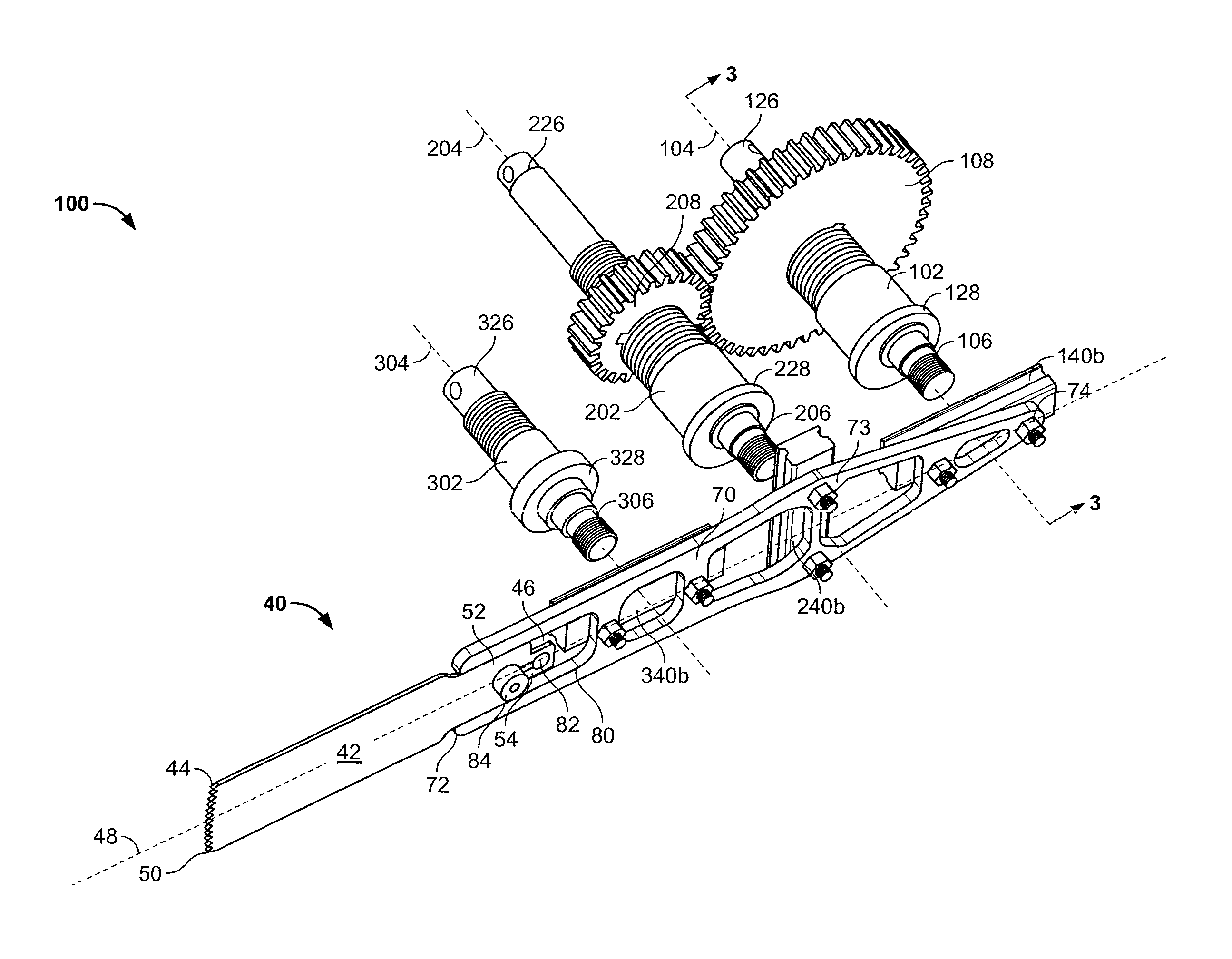
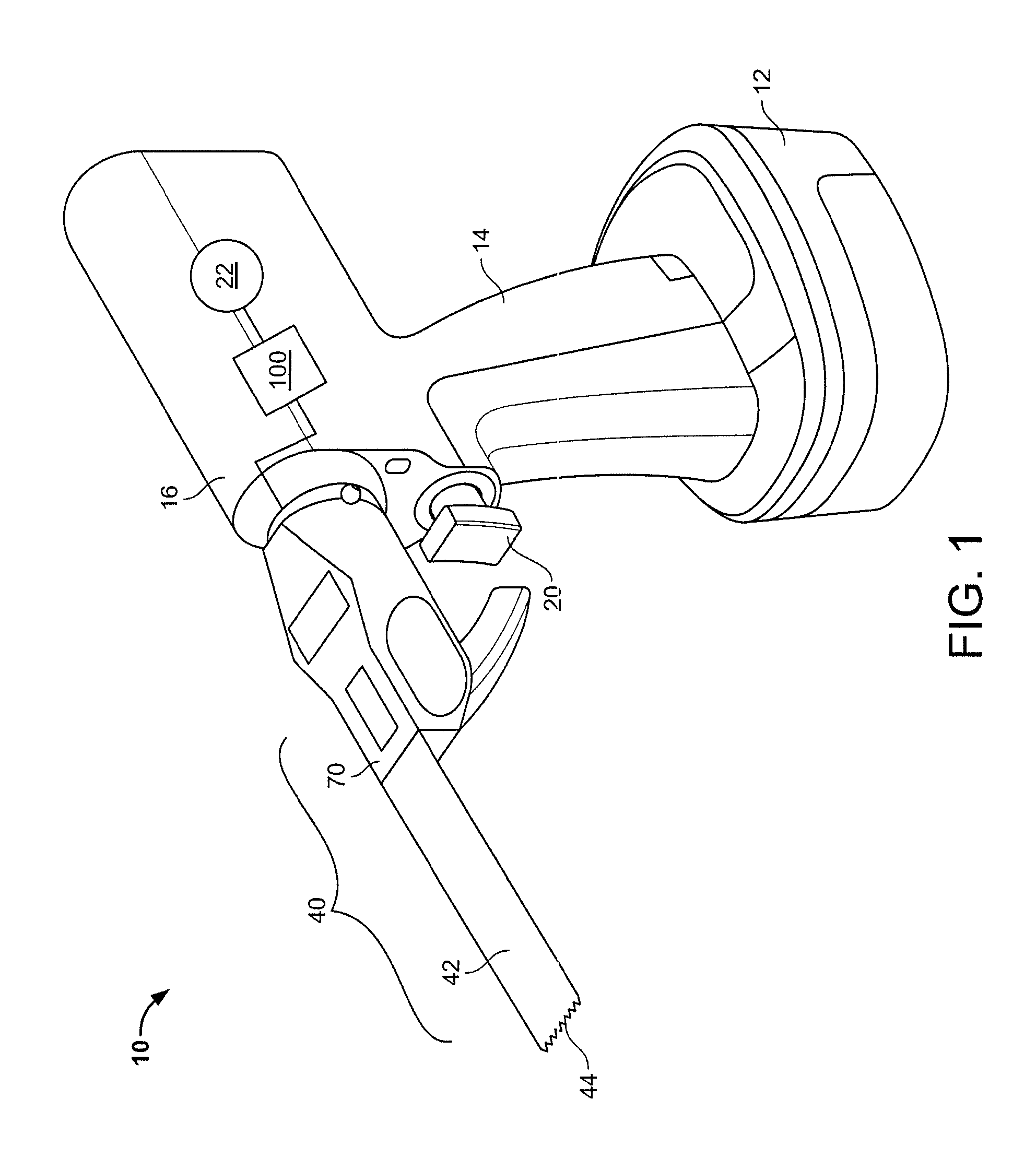
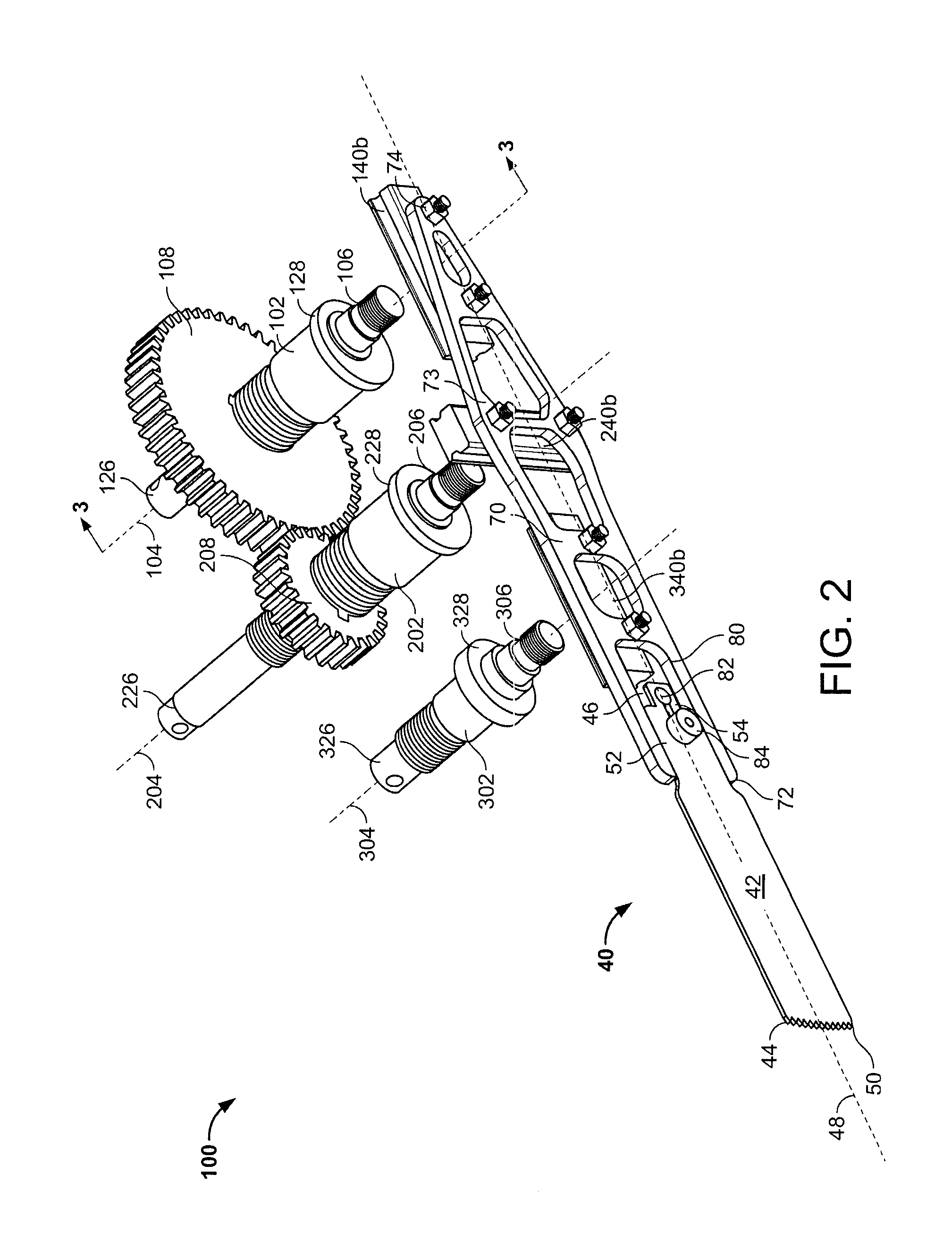
[0024]Referring now to FIGS. 1-4, the sagittal saw 10 is a hand-held device that includes a motor housing 16 and a handle 14 extending from an end of the housing 16. In this embodiment, a battery pack 12 is detachably secured to an end of the handle 14 and serves as a power source for a motor 22 disposed within the housing 16. A gear assembly 100 is also disposed within the housing 16 and connects the motor 22 to a blade assembly 40. The gear assembly 100 is driven by the motor 22, and in turn drives the blade assembly 40 in such a way as to increase cutting speed and reduce heat generation by the saw 10 as compared to some conventional sagittal saws. As discussed further below, a cutting edge 44 of a saw blade 42 is driven by the gear assembly 100 along a planar cyclic path that is generally in the form of a figure-eight, or, in other words, a closed planar loop curve consisting of two lobes meeting at a node. The lobes may be symmetric or asymmetric.

[0025]The cyclic figure-eight m...


PUM


Abstract

A sagittal saw includes a blade and an actuator configured to drive the blade. The blade includes a first end, a second end opposed to the first end, and a longitudinal axis extending between the first end and second end. The blade first end extends transverse to the longitudinal axis, and its movement defines a blade path. The blade path comprises a closed plane curve consisting of two loops meeting at a node ie, a figure-eight, whereby the blade path crosses over itself. The actuator includes a gear assembly configured to cyclically drive the blade so that the blade path includes multiple impulsive thrusts along the longitudinal axis in each blade path cycle. In addition, the blade cuts the work piece in both a first direction and a second direction in each blade cycle, the second direction opposed to the first direction.

Description

CROSS REFERENCE TO RELATED APPLICATIONS[0001]This application is a National Stage of International Application No. PCT / US2012 / 040986 filed on Jun. 6, 2012, which claims priority to U.S. Provisional Application No. 61 / 495,678, filed Jun. 10, 2011, the contents of which are hereby incorporated in their entirety.BACKGROUND OF THE INVENTION[0002]Sagittal bone saws function through angular oscillation of the saw cutting blade, and are used primarily in applications that require plunge cutting of bone. However, when used at a high cutting rate, sagittal saws can sometimes generate a significant amount of heat, damaging or destroying bone cells in the immediate area of the cut. Damage to bone cells is undesirable since it can delay patient recovery time and reduce the effectiveness of the surgical procedure. One alternative to high cutting rates includes application of an impulsive thrust force wherein the cutting blade includes motion normal to, and directed into, the bone surface.SUMMARY...

Claims


Application Information

Patent Timeline
Patent Type & Authority Patents(United States)
IPC IPC(8): A61B17/14
CPCA61B17/142A61B17/14
Inventor KELLY, MATTHEW P.LANNIN, TIMOTHY B.JAMES, THOMAS P.
Owner TUFTS UNIV
Learn More