Method and arrangement for refining copper concentrate

a technology of copper concentrate and refining method, which is applied in the direction of electric furnaces, lighting and heating apparatus, furnaces, etc., can solve the problems of low foaming potential and unnecessary slag storage in the settler of suspension smelting furnaces, and achieve the effect of simplifying the layou

Active Publication Date: 2017-02-28
METSO METALS OY
View PDF9 Cites 0 Cited by
  • Summary
  • Abstract
  • Description
  • Claims
  • Application Information

AI Technical Summary

Benefits of technology

[0015]The invention is based on feeding both slag and blister from the suspension smelting furnace to the slag cleaning furnace. By feeding both slag and blister from the suspension smelting furnace to the slag cleaning furnace will a greater amount of thermal energy be fed to the slag cleaning furnace in comparison to a situation where only slag is fed from the suspension smelting furnace to the slag cleaning furnace, as in the prior art arrangement shown in FIG. 1. This greater amount of thermal energy can be used for melting material possible having been solidified in the slag cleaning furnace. Because both slag and blister from the suspension smelting furnace to the slag cleaning furnace, a slag storage in the settler of the suspension smelting furnace is unnecessarily. Additionally it is unnecessary to separate blister from slag in the settler, because both slag and blister are fed from the suspension smelting furnace to the slag cleaning furnace. Because of this, the settler may be made smaller, which reduces the costs for the suspension smelting furnace. If blister and slag are tapped directly into the slag cleaning furnace with very low bath level in the flash, then foaming potential will be low. The suspension smelting furnaces can be run with lower oxygen potential, as the foaming tendency will be lower. This means lower off-gas volumes and savings in operational costs in the off-gas line. Also less reducing work for the slag cleaning furnace, and therefore less energy consumption
[0019]Feeding blister and / or slag having temperature between 1250 and 1400° C. from the settler of the suspension smelting furnace reduces the need for thermal energy to be fed to the slag cleaning furnace for the reduction process, because the blister and / or the slag that is fed to the suspension smelting furnace is over hot i.e. contains excess thermal energy in addition to that needed for the reaction in the suspension smelting furnace. This excess thermal energy can be used in the reduction process in the slag cleaning furnace. Especially if an electric furnace is used as a slag cleaning furnace, this is particularly advantageous, because it is less expensive to create thermal energy by a suspension smelting furnace than to create thermal energy with an electric furnace.
[0022]Another advantage achievable with the method and the arrangement according to the invention is that it makes possible a simplified layout in comparison with the prior art method and arrangement shown in FIG. 1. For example in the embodiments shown in FIG. 2, which comprises anode furnaces, material is only fed into the slag cleaning furnace from the suspension smelting furnace and material is only fed into the anode furnaces from the slag cleaning furnace.

Problems solved by technology

Because both slag and blister from the suspension smelting furnace to the slag cleaning furnace, a slag storage in the settler of the suspension smelting furnace is unnecessarily.
If blister and slag are tapped directly into the slag cleaning furnace with very low bath level in the flash, then foaming potential will be low.

Method used


Image

  • Method and arrangement for refining copper concentrate
  • Method and arrangement for refining copper concentrate
  • Method and arrangement for refining copper concentrate

Examples


Embodiment Construction

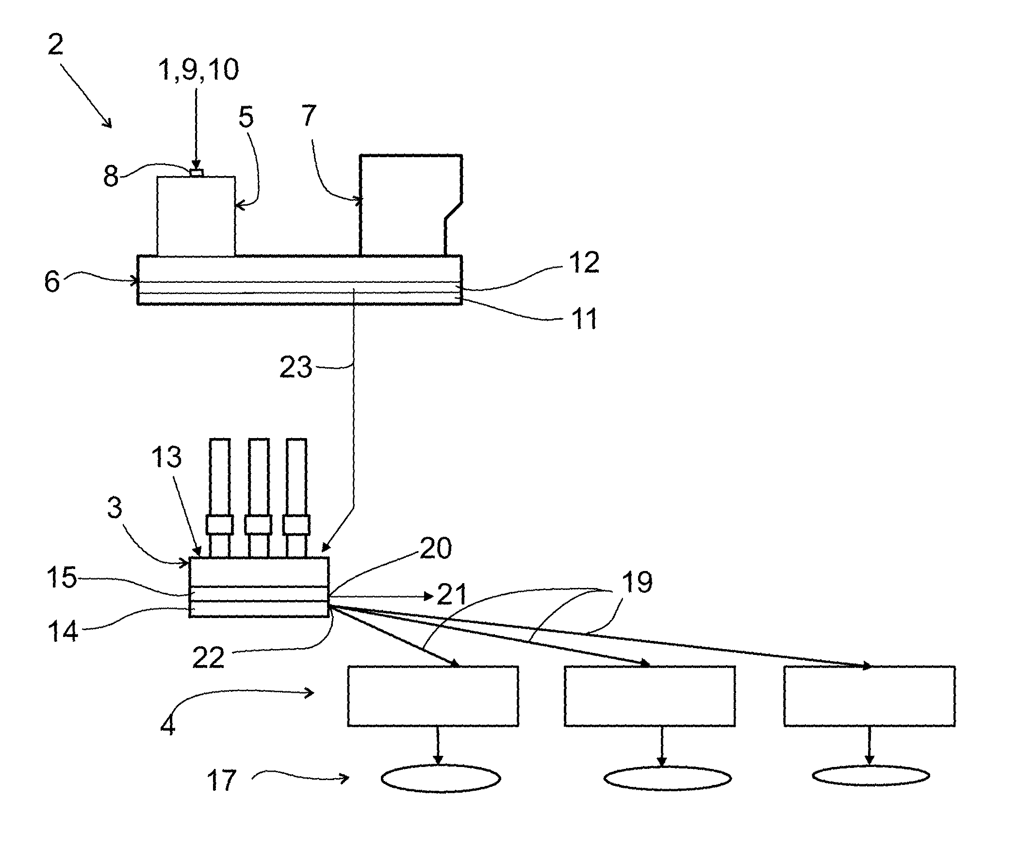
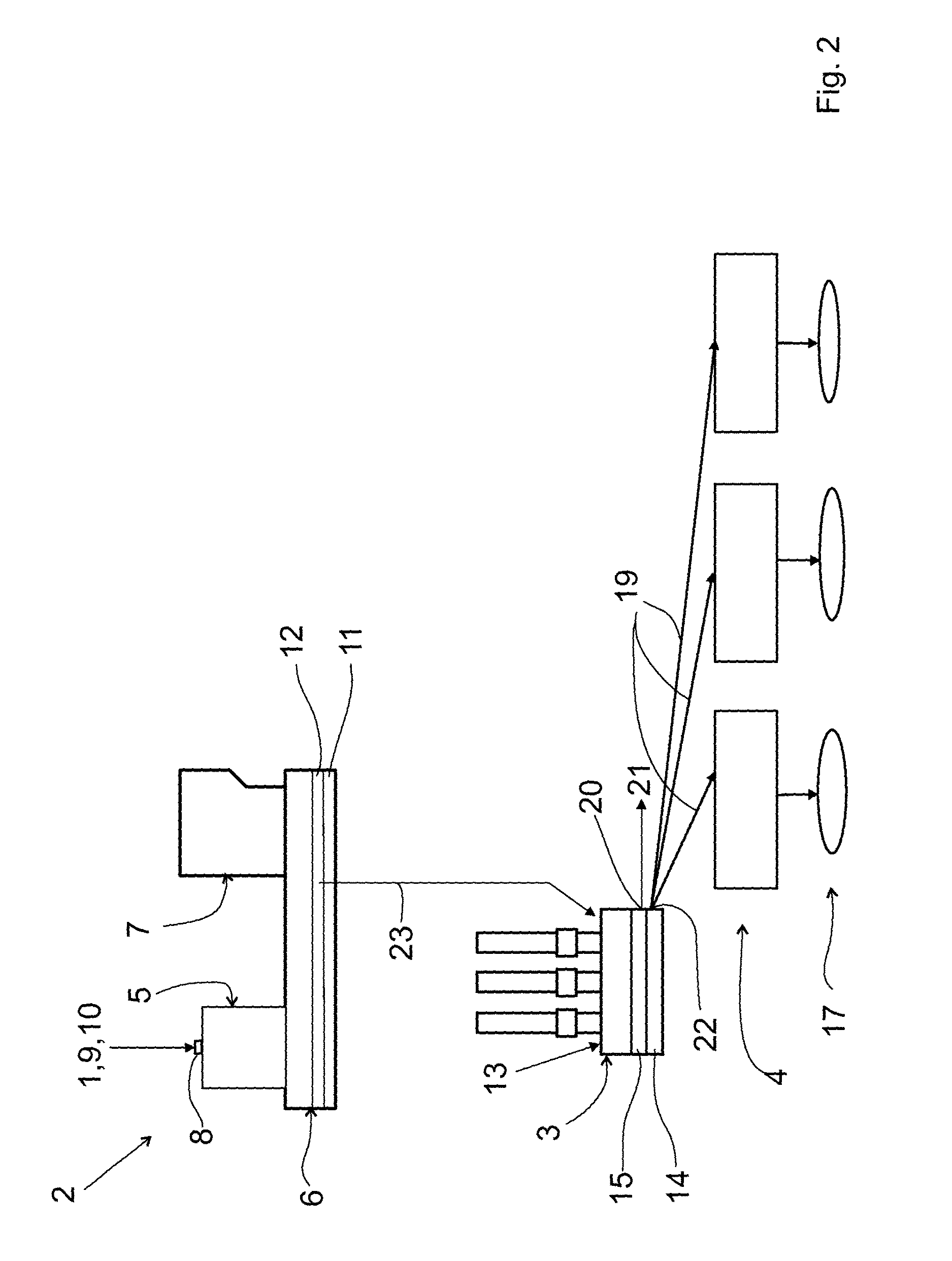
[0029]The invention relates to a method and to an arrangement for refining copper concentrate 1.

[0030]First the method refining copper concentrate 1 and preferred embodiments and variants thereof will be described in greater detail.

[0031]The method comprises using a suspension smelting furnace 2 comprising a reaction shaft 5, a settler 6, and preferably, but not necessarily, an uptake 7.

[0032]The reaction shaft 5 of the suspension smelting furnace 2 is provided with a concentrate burner 8 for feeding copper concentrate 1 such as copper sulfide concentrate and / or copper matte and additionally at least reaction gas 9, and preferable also flux 10, into the reaction shaft 5 of the suspension smelting furnace 2 to obtain a blister layer 11 containing blister and a first slag layer 12 containing slag on top of the blister layer 11 in the settler 6 of the suspension smelting furnace 2.

[0033]The method comprises additionally using a slag cleaning furnace 3. The method comprises preferably u...


PUM

PropertyMeasurementUnit
temperatureaaaaaaaaaa
thermal energyaaaaaaaaaa

Abstract

The invention relates to a method and to an arrangement for refining copper concentrate. The arrangement includes a suspension smelting furnace comprising a reaction shaft, and a settler. The reaction shaft is provided with a concentrate burner for feeding copper concentrate such as copper sulfide concentrate and / or copper matte and additionally at least reaction gas into the reaction shaft to obtain a blister layer containing blister and a first slag layer containing slag on top of the blister layer in the settler, and a slag cleaning furnace. The arrangement includes a feeder configured for feeding blister from the blister layer in the settler and for feeding slag from the first slag layer in the settler into the slag cleaning furnace.

Description

CROSS-REFERENCE TO RELATED APPLICATIONS[0001]This is a national stage application filed under 35 USC 371 based on International Application No. PCT / FI2013 / 050646 filed Jun. 12, 2013 and claims priority under 35 USC 119 of Finnish Patent Application No. 20125653 filed Jun. 13, 2012.STATEMENT REGARDING FEDERALLY SPONSORED RESEARCH OR DEVELOPMENT[0002]Not Applicable.THE NAMES OF THE PARTIES TO A JOINT RESEARCH AGREEMENT[0003]Not Applicable.INCORPORATION-BY-REFERENCE OF MATERIAL SUBMITTED ON A COMPACT DISC OR AS A TEXT FILE VIA THE OFFICE ELECTRONIC FILING SYSTEM (EFS-WEB)[0004]Not Applicable.STATEMENT REGARDING PRIOR DISCLOSURES BY THE INVENTOR OR A JOINT INVENTOR[0005]Not Applicable.BACKGROUND OF THE INVENTION[0006]Not Applicable.FIELD OF THE INVENTION[0007]The invention relates to a method for refining copper concentrate.[0008]The invention also relates to an arrangement for refining copper concentrate.[0009]The method includes using a suspension smelting furnace and the arrangement ...

Claims


Application Information

Patent Timeline
Patent Type & Authority Patents(United States)
IPC IPC(8): F27B19/04C22B7/04C22B4/04C22B15/02C22B15/00C22B4/08
CPCC22B15/005C22B4/04C22B4/08C22B7/04C22B15/0032C22B15/0039C22B15/0047C22B15/0052F27B19/04C22B15/006
Inventor AHOKAINEN, TAPIOBJORKLUND, PETERJOKINEN, TUOMORANNIKKO, HARRIMETSARINTA, MAIJALAHTINEN, MARKKU
Owner METSO METALS OY
Why Eureka
Try Eureka