

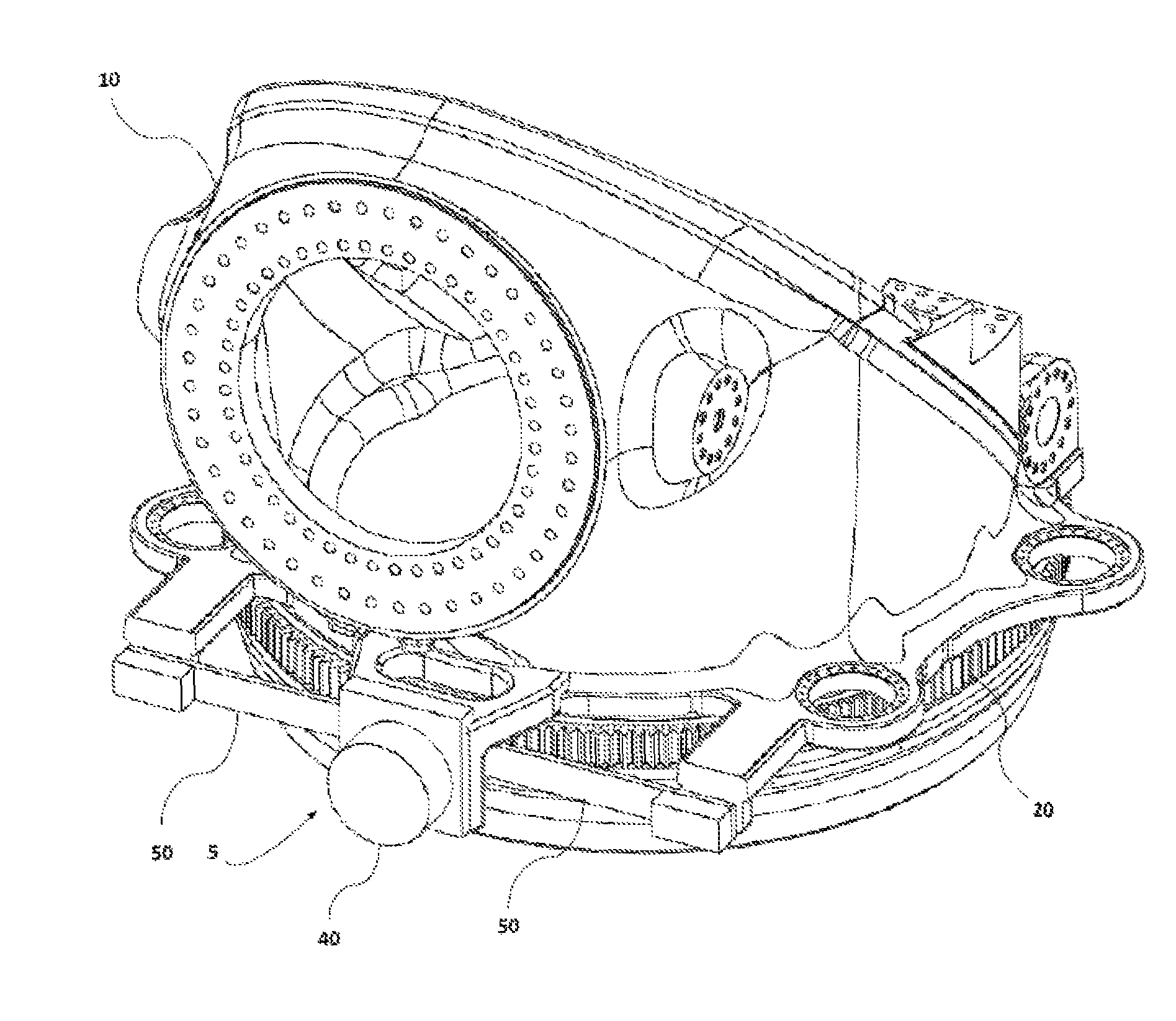
Yaw brakes for wind turbines
a technology for wind turbines and brakes, which is applied in the direction of wind turbine control, wind energy generation, motors, etc., can solve the problems of premature failure of the brake callipers themselves, the lining of the brake callipers does not have a constant friction coefficient, and the friction coefficient may be affected, so as to reduce the cost of the yaw brake and prevent potential contamination.
- Summary
- Abstract
- Description
- Claims
- Application Information
AI Technical Summary
Benefits of technology
Problems solved by technology
Method used
Image

Examples
Embodiment Construction
[0035]In the following description, numerous specific details are set forth in order to provide a thorough understanding of the present invention. It will be understood by one skilled in the art however, that the present invention may be practiced without some or all of these specific details. In other instances, well known elements have not been described in detail in order not to unnecessarily obscure the description of the present invention.
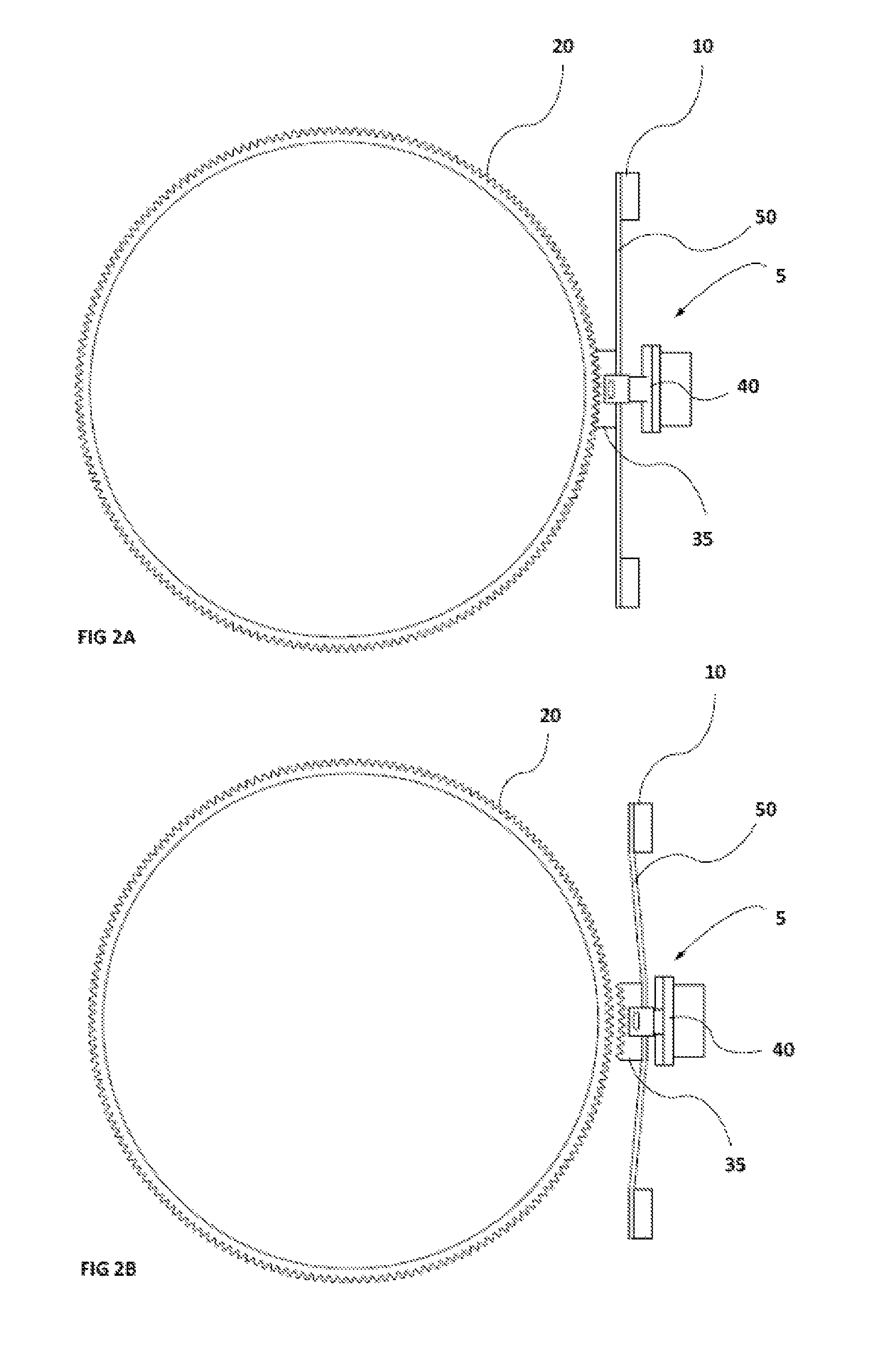
[0036]FIGS. 2A and 2B schematically illustrate a detail of a yaw system having a yaw brake according to an embodiment in brake and non-brake position, respectively; In particular, FIG. 2A shows a yaw brake 5, according to an example, actuating on a circular annular gear 20. FIG. 2B shows yaw brake 5 in a non-brake position, i.e. while the nacelle is rotating.
[0037]Yaw brake 5 includes a locking part 35, a piston 40 and a tangential beam 50. Locking part 35 has a negative toothed profile with respect to the tooth profile of annular gear 20. As ...
PUM
 Abstract
Description
Claims
Application Information