Tank overflow protection system and method

a technology of tank overflow and protection system, which is applied in the direction of liquid/fluent solid measurement, instruments, machines/engines, etc., can solve the problems of inaccurate level measurement and possible overflow of the tank, and achieve the effect of accurate level measuremen

Active Publication Date: 2017-02-28
HONEYWELL INT INC
View PDF18 Cites 0 Cited by
  • Summary
  • Abstract
  • Description
  • Claims
  • Application Information

AI Technical Summary

Benefits of technology

[0010]The fluid level can be compensated for additional changes due to change in fluid density. The compensation with respect to a tank level error can be performed in the main processor printed wire assembly. The differential pressure sensor can be employed to calculate the difference in pressure between the top and the bottom of the tank. Utilizing a length of cable to maintain transmission of the pressure and temperature measurement can separate the transmitter and the main processor printed wire assembly. The apparatus provides an accurate level measurement by assessing both the pressure and temperature for density compensation.

Problems solved by technology

As temperature increases, the fluid density decreases and the level rises without an accompanying increase in differential pressure which leads to an inaccurate level measurement and possibly overflow of the tank.

Method used


Image

  • Tank overflow protection system and method
  • Tank overflow protection system and method
  • Tank overflow protection system and method

Examples


Embodiment Construction

[0016]The particular values and configurations discussed in these non-limiting examples can be varied and are cited merely to illustrate at least one embodiment and are not intended to limit the scope thereof.

[0017]The embodiments will now be described more fully hereinafter with reference to the accompanying drawings, in which illustrative embodiments of the invention are shown. The embodiments disclosed herein can be embodied in many different forms and should not be construed as limited to the embodiments set forth herein; rather, these embodiments are provided so that this disclosure will be thorough and complete and will fully convey the scope of the invention to those skilled in the art. Like numbers refer to like elements throughout. As used herein, the term “and / or” includes any and all combinations of one or more of the associated listed items.

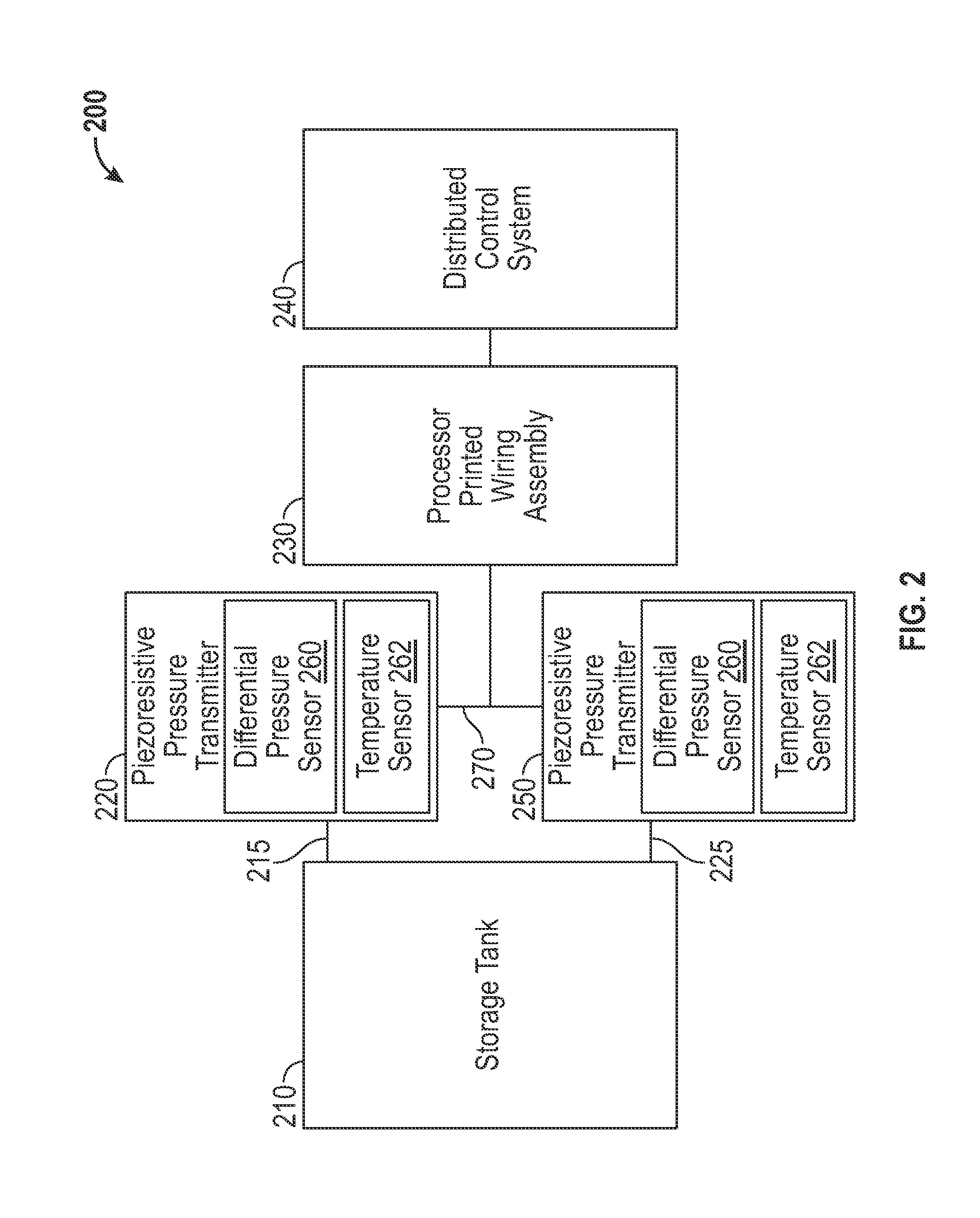
[0018]FIG. 2 illustrates a block diagram of a tank overflow protection system 200, in accordance with the disclosed embodiments. The...


PUM


Abstract

A tank overflow protection system and method for measuring process temperature and pressure utilizing one or more piezoresistive pressure transmitters. The piezoresistive pressure transmitter includes a differential pressure sensor and a temperature sensor. Data from the piezoresistive pressure transmitters can be digitally communicated via a cable. The pressure transmitters convert signals indicative of temperature and pressure to a digital value and transmit the signals to a main processor printed wire assembly for final compensation, diagnostics, and transmission to a distributed control system. A differential pressure can be calculated by subtracting two digital pressure measurement values. The temperature measurement can be employed to calculate any changes in density for a user-defined reference value.

Description

TECHNICAL FIELD[0001]Embodiments are generally related to transmitter devices and methods. Embodiments are also related to pressure and temperature sensing devices and techniques. Embodiments are additionally related to tank overflow protection systems and methods.BACKGROUND OF THE INVENTION[0002]Liquid level in a storage tank can be controlled by measuring pressure at two measurement points, for example, one point above the fluid and another near the bottom of the tank. The fluid level can be calculated utilizing differential pressure and fluid density data. As temperature increases, the fluid density decreases and the level rises without an accompanying increase in differential pressure which leads to an inaccurate level measurement and possibly overflow of the tank.[0003]FIG. 1 illustrates a prior art tank overflow protection system 100 that includes a remote seal transmitter 110 connected to a storage tank 150 for measuring liquid level within the tank 150. The remote seal trans...

Claims


Application Information

Patent Timeline
Patent Type & Authority Patents(United States)
IPC IPC(8): G01F23/18G01F23/00
CPCG01F23/185G01F23/0076G01F23/804
Inventor HERSHEY, GEORGE
Owner HONEYWELL INT INC
Why Eureka
Try Eureka