Method of producing an electrically conductive roller from a rubber foam tube

a technology of rubber foam and production method, which is applied in the direction of electrographic process, instruments, other domestic objects, etc., can solve the problems of reducing the roller body of electrically conductive rollers is liable to gradually increase to significantly change after production, and the roller body is often rejected. to achieve the effect of improving the production yield of electrically conductive rollers

Inactive Publication Date: 2017-03-07
SUMITOMO RUBBER IND LTD
View PDF25 Cites 0 Cited by
  • Summary
  • Abstract
  • Description
  • Claims
  • Application Information

AI Technical Summary

Benefits of technology

[0031]According to the present invention, the production yield of the electrically conductive roller can be improved over the conventional methods. Further, the production method ensures efficient production of the rubber foam tube for the roller body.

Problems solved by technology

Where the electrically conductive roller is produced by cutting and polishing the rubber foam tube formed through the foaming and the crosslinking under the conventional conditions disclosed in Patent Literatures 1 to 3 with the use of the continuous crosslinking apparatus, however, the outer diameter of the roller body of the electrically conductive roller is liable to gradually increase to significantly change after the production.
Therefore, even if the roller body is accurately finished so as to have a predetermined outer diameter in the polishing step in a production plant, for example, the roller body is often rejected due to an outer diameter dimensional error at customer's acceptance inspection.
This may significantly reduce the production yield of the electrically conductive roller.
Even if the post-polishing outer diameter of the roller body is specified based on an expected dimensional change, the dimensional error occurs due to variation in the time of the customer's acceptance inspection.
This also results in reduction in the production yield of the electrically conductive roller.

Method used


Image

  • Method of producing an electrically conductive roller from a rubber foam tube
  • Method of producing an electrically conductive roller from a rubber foam tube

Examples


example 1

Preparation of Electrically Conductive Rubber Composition

[0147]A rubber component was prepared by blending 70 parts by mass of an NBR (a lower acrylonitrile content NBR JSR N250SL available from JSR Co., Ltd. and having an acrylonitrile content of 20%), 10 parts by mass of an EPDM (ESPRENE (registered trade name) EPDM505A available from Sumitomo Chemical Co., Ltd) and 20 parts by mass of an ECO (HYDRIN (registered trade name) T3108 available from Zeon Corporation).

[0148]A rubber composition was prepared by blending ingredients shown below in Table 1 with 100 parts by mass of the rubber component, and kneading the resulting mixture at 80° C. for 3 to 5 minutes by means of an enclosed kneader.

[0149]

TABLE 1IngredientsParts by massFiller10Foaming agent4Acid accepting agent3Crosslinking agent1.5Accelerating agent DM0.5Accelerating agent TS0.5Acceleration assisting agent5

[0150]The ingredients shown in Table 1 are as follows. The amounts (parts by mass) of the ingredients shown in Table 1 ...

example 2

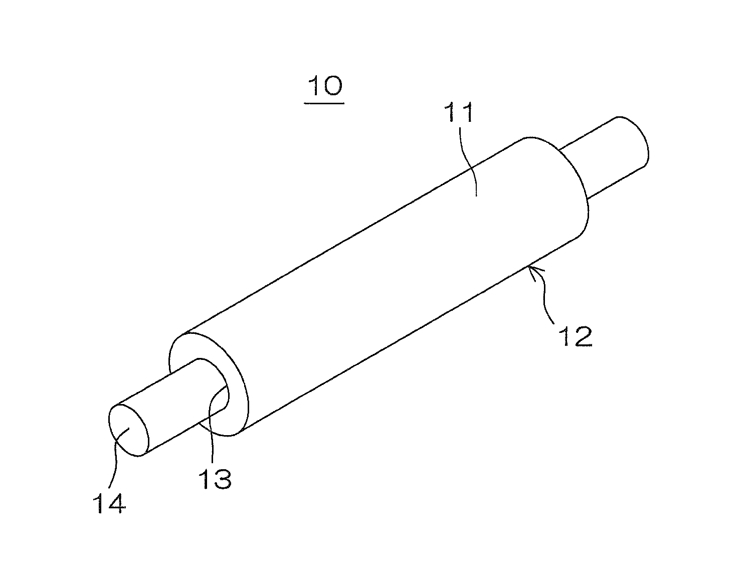
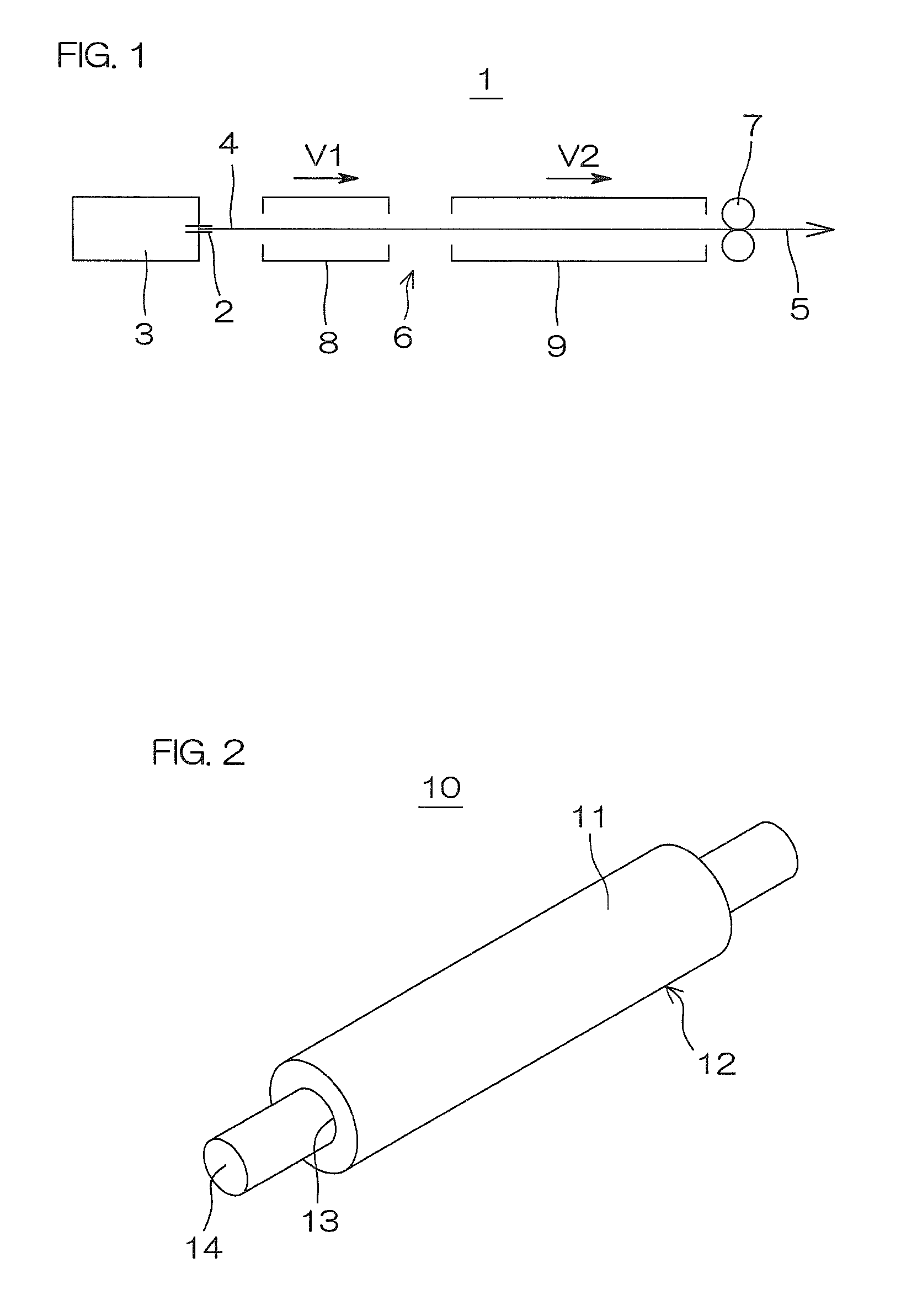
[0157]A rubber foam tube was produced in substantially the same manner as in Example 1, except that the tubular body 4 was passed through the microwave crosslinking device 8 at a speed V1 of 7.5 m / min and passed through the hot air crosslinking device 9 at a speed V2 of 9.5 m / min, and the ratio V2 / V1 between the speeds V2 and V1 was 1.27. Then, the electrically conductive roller was produced by using the rubber foam tube thus produced.

example 3

[0158]An electrically conductive rubber composition was prepared in substantially the same manner as in Example 1, except that the amount of the foaming agent was 2 parts by mass based on 100 parts by mass of the rubber component. A rubber foam tube was produced in substantially the same manner as in Example 1, except that the electrically conductive rubber composition thus prepared was used, and the tubular body 4 was passed through the microwave crosslinking device 8 at a speed V1 of 6.5 m / min and passed through the hot air crosslinking device 9 at a speed V2 of 10.2 m / min, and the ratio V2 / V1 between the speeds V2 and V1 was 1.57. Then, the electrically conductive roller was produced by using the rubber foam tube thus produced.


PUM

PropertyMeasurementUnit
speed V1aaaaaaaaaa
speed V1aaaaaaaaaa
temperatureaaaaaaaaaa

Abstract

A rubber foam tube (5) is produced by extruding a rubber composition into a tubular body (4) and feeding the tubular body (4) in an elongated state without cutting to pass the tubular body (4) through a microwave crosslinking device (8) and then through a hot air crosslinking device (9) for continuously foaming and crosslinking the rubber composition. At this time, a ratio V2 / V1 between a speed V2 at which the tubular body (4) passes through the hot air crosslinking device (9) and a speed V1 at which the tubular body (4) passes through the microwave crosslinking device (8) is not less than 1.0 and not greater than 1.6.

Description

TECHNICAL FIELD[0001]The present invention relates to a rubber foam tube production method, an electrically conductive roller including a roller body produced from an electrically conductive rubber composition by the production method, and an image forming apparatus incorporating the electrically conductive roller.BACKGROUND ART[0002]In an electrophotographic image forming apparatus such as a laser printer, an electrostatic copying machine, a plain paper facsimile machine or a printer-copier-facsimile multifunction machine, for example, an image is generally formed on a surface of a sheet (the term “sheet” is herein defined to include a paper sheet, a plastic film such as an OHP film and the like, and this definition is effective in the following description) through the following process steps.[0003]First, a surface of a photoreceptor body having photoconductivity is evenly electrically charged and, in this state, exposed to light, whereby an electrostatic latent image correspondin...

Claims


Application Information

Patent Timeline
Patent Type & Authority Patents(United States)
IPC IPC(8): G03G15/00B29C47/00B29C47/88B29C35/10B29C47/92B29C35/06B29D23/00B29C35/08B29C35/04B29C48/09B29C48/91B29C48/92
CPCG03G15/00B29C35/06B29C35/10B29C47/0023B29C47/0042B29C47/882B29C47/8805B29C47/92B29C35/045B29C2035/0855B29C2947/92704B29C2947/92714B29C2947/92923B29D23/001Y10T29/49563G03G15/0233G03G15/0818G03G15/1685B29C48/09B29C48/0012B29C48/91B29C48/92B29C48/9115B29C2948/92704B29C2948/92714B29C2948/92923
Inventor YAMAGUCHI, TAKUYAYABUSHITA, SHUNICHITANIO, YUSUKE
Owner SUMITOMO RUBBER IND LTD
Why Eureka
Try Eureka