Reflector, surface-emitting laser, solid-state laser device, optoacoustic system, and image-forming apparatus

a surface-emitting laser and laser technology, applied in semiconductor lasers, instruments, electrographic processes, etc., can solve problems such as crystal defects, and achieve the effect of wide reflection band and high reflectivity

Active Publication Date: 2017-03-07
CANON KK
View PDF10 Cites 1 Cited by
  • Summary
  • Abstract
  • Description
  • Claims
  • Application Information

AI Technical Summary

Benefits of technology

[0010]According to the present invention, the following reflector can be obtained: a reflector which includes AlGaN layers, InGaN layers, and GaN lavers placed therebetween and which has high reflectivity and a wide reflection band.

Problems solved by technology

The reduction in loss by increasing the reflectivity of the DBRs is a challenge to increase the laser power of the VCSEL.
However, in the case of using two different types of materials having different lattice strains, there is a problem. in that crystal defects are induced.

Method used


Image

  • Reflector, surface-emitting laser, solid-state laser device, optoacoustic system, and image-forming apparatus
  • Reflector, surface-emitting laser, solid-state laser device, optoacoustic system, and image-forming apparatus
  • Reflector, surface-emitting laser, solid-state laser device, optoacoustic system, and image-forming apparatus

Examples


first embodiment

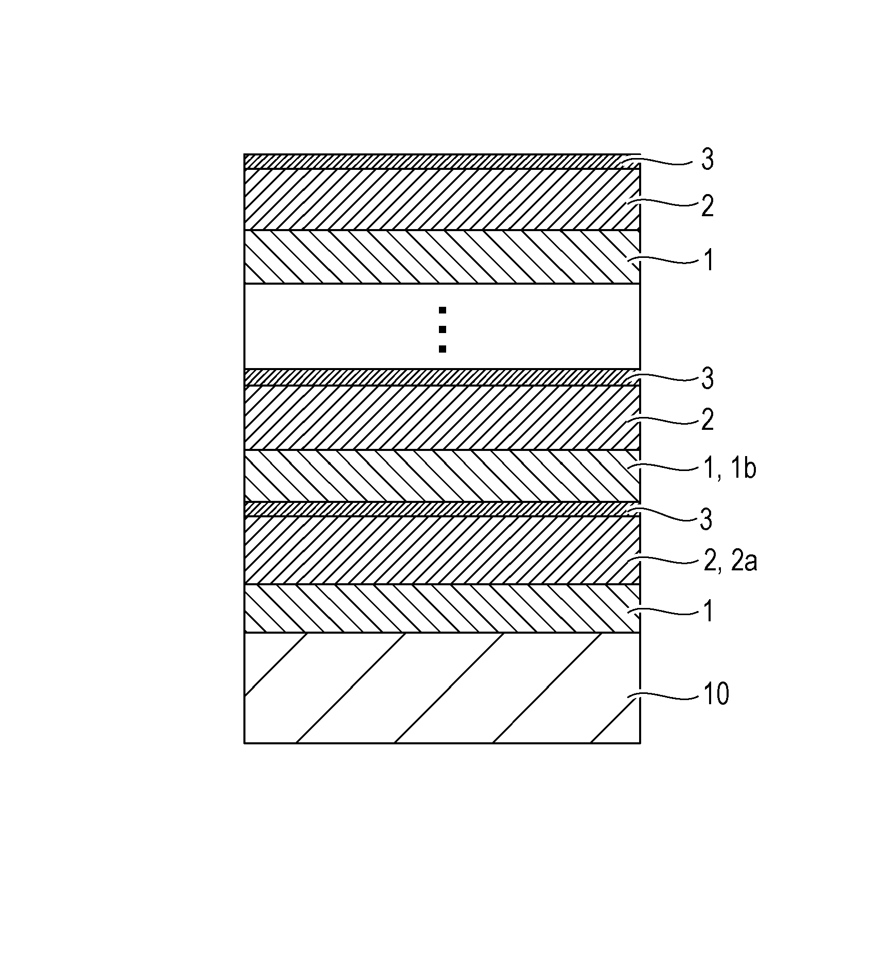
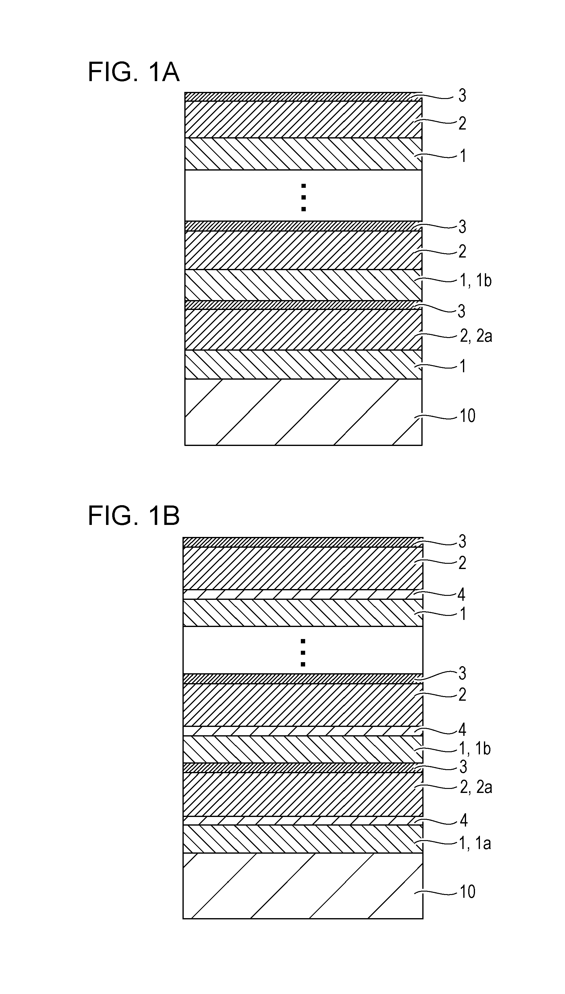
[0020]A reflector according to a first embodiment of the present invention includes a substrate containing GaN, first layers containing AlxGa1-xN, second layers containing InyGa1-yN, and third layers containing GaN. The first, second, and third layers are stacked on the substrate. The third layers are placed between at least some of the first and second layers. The first layers, which contain AlxGa1-xN, have tensile strain and the second layers, which contain InyGa1-yN, have compressive strain. The first and second layers are alternately stacked; hence, strain can be compensated for. The first layers are those epitaxially grown on the substrate, which contains GaN. The following values are set to be substantially equal to each other: the absolute value of the product of the strain ε1 and thickness tl of the first layers, which. have tensile strain, and the absolute value of the product of the strain ε2 and thickness t2 of the second layers, which have compressive strain. This compen...

second embodiment

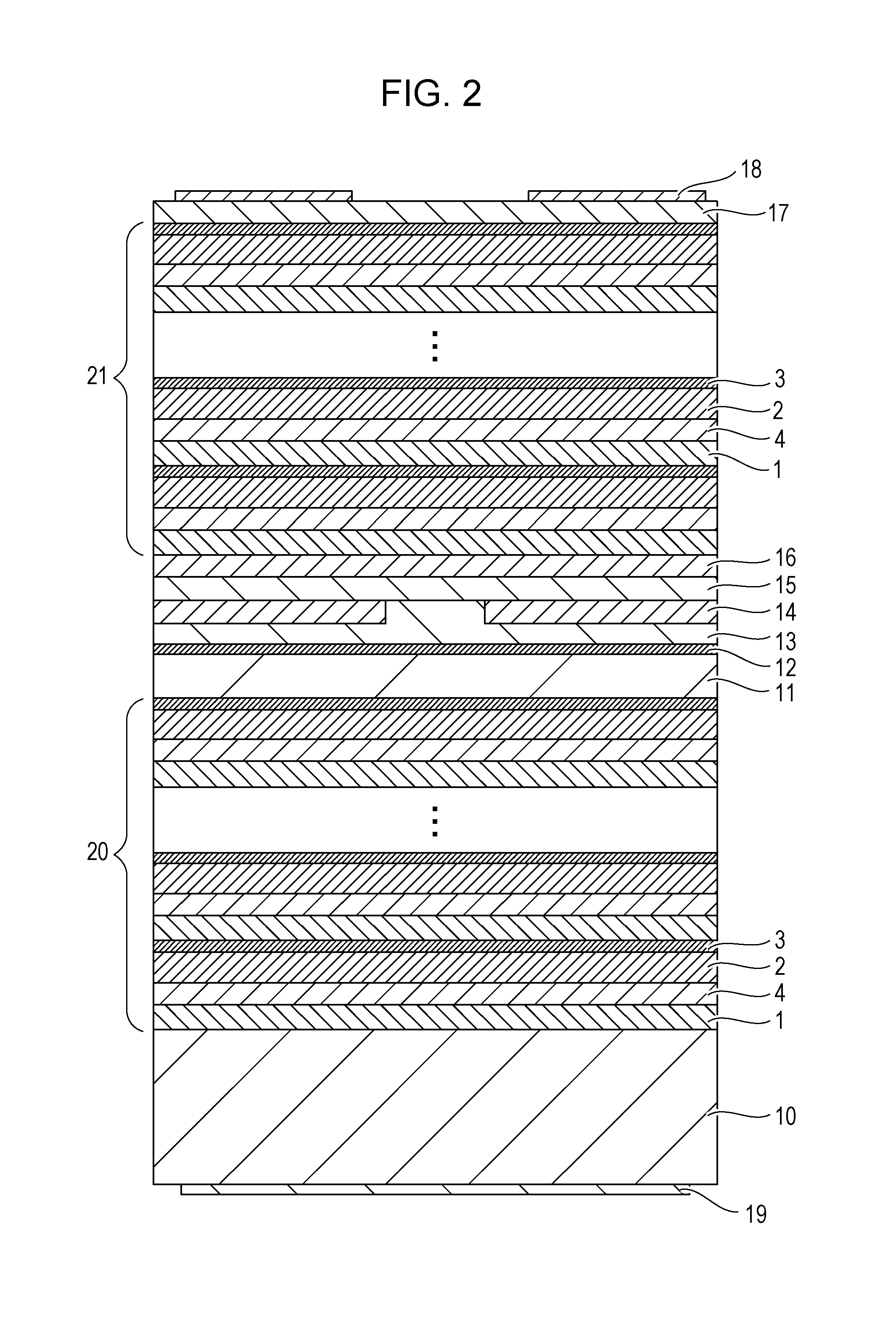
[0047]In this embodiment, a vertical-cavity surface-emitting laser (VCSEL) including a reflector identical to the reflector according to the first embodiment is described. FIG. 2 is a schematic sectional view of an example of the VCSEL. The VCSEL includes a pair of reflectors 20 and 21 and an active layer 12 placed between the reflectors 20 and 21. Referring to FIG. 2, both the reflectors 20 and 21 are identical to the reflector described in the first embodiment with reference to FIG. 1B. At least one of the reflectors 20 and 21 may be identical to the reflector described in the first embodiment with reference to FIG. 1B.

[0048]The VCSEL is further described in detail. The reflector 20 is placed on a substrate 10. An electrode 19 is placed on the side of the substrate 10 opposite to the reflector 20. A spacer layer 11, the active layer 12, and a spacer layer 13 are placed on the reflector 20 in that order from the substrate 10.

[0049]The active layer 12 has a three-period InGaN / GaN qu...

third embodiment

[0056]In this embodiment, a solid-state laser device 110 including the vertical-cavity surface-emitting laser (VCSEL) according to the second embodiment is described with reference to FIG. 3. The solid-state laser device 110 includes a light source 111 including the VCSEL, a solid-state laser medium 113 excited by light emitted by the VCSEL, and two reflective members 115a and 115b. The light source 111 may be one in which an array of VCSELs identical to the VCSEL are integrated for the purpose of increasing the power.

[0057]Light 112, emitted. from the light source 111, having the laser emission wavelength of the VCSEL is applied to the solid-state laser medium 113. The solid-state laser medium 113 absorbs the light 112 to emit light 114 in association with laser transition. The light 114 is repeatedly reflected by the reflective members 115a and 115b and therefore the solid-state laser device 110 lases. A solid-state laser beam 116 passing through the reflective member 115b is emit...


PUM


Abstract

In a reflector including an AlGaN layer, an InGaN layer, and a GaN layer placed therebetween, high reflectivity and a wide reflection band are achieved. A reflector includes a substrate containing GaN; first layers containing AlxGa1-xN; second layers containing InyGa1-yN; and a third layer containing GaN, the first, second, and third layers being stacked on the substrate. The first and second layers are alternately stacked, the third layer is placed between one of the first layers and one of the second layers, x and y satisfy a specific formula, the first layers have a thickness less than the thickness of the second layers, and the second layers have an optical thickness of λ / 8 to 3λ / 8, where λ is the central wavelength of the reflection. band of the reflector.

Description

CROSS-REFERENCE TO RELATED APPLICATIONS[0001]This application is a National Stage filing International Application No. PCT / JP2014 / 071140 filed Aug. 5, 2014, which claims the benefit of Japanese Patent Application No. 2013-212906 filed Oct. 10, 2013, the disclosures of each of which are hereby incorporated by reference herein in their entirety.TECHNICAL FIELD[0002]The present invention relates to a reflector, a surface-emitting laser, a solid-state laser device, an optoacoustic system, and an image-forming apparatus.BACKGROUND ART[0003]A vertical-cavity surface-emitting laser (VCSEL) is a laser in which a pair of reflectors and an active layer interposed therebetween form a resonator perpendicular to a substrate. The reflectors used are distributed Bragg reflectors (DBRs) each including several layers, formed by depositing two types of materials with different refractive indexes, having an optical thickness corresponding to a ¼ wavelength. The reduction in loss by increasing the refl...

Claims


Application Information

Patent Timeline
Patent Type & Authority Patents(United States)
IPC IPC(8): H01S5/183B41J2/447H01S5/02B41J2/47G03G15/04H01S3/0941H01L21/02
CPCH01S5/18361B41J2/447B41J2/473G03G15/04036H01S5/0212H01L21/0254H01L21/0262H01L21/02458H01L21/02507H01S3/0941
Inventor KAWASHIMA, TAKESHI
Owner CANON KK
Why Eureka
Try Eureka