Rail mounting system

a mounting system and rail technology, applied in the direction of load accommodation, fishing, vessel construction, etc., can solve the problems of severe limited adjustment, and the orientation of the assembled bracket including accessories with respect to the boat rail is not adjustable about the rail

Active Publication Date: 2017-03-28
HOBIE CAT IP LLC
View PDF9 Cites 9 Cited by
  • Summary
  • Abstract
  • Description
  • Claims
  • Application Information

AI Technical Summary

Benefits of technology

[0007]The combination comprising a tubular handrail on a watercraft having more than four essentially identical surfaces each extending along the longitudinal dimension to form the exterior surface of the tubular handrail and a clamping system having interior surfaces for extending around said tubular handrail such that said surfaces prevent rotation of the clamping system about the rail when the clamping system is closed and provide incremental adjustability of the orientation of the clamping system about said tubular handrail.
[0008]A watercraft comprising the combination comprising a tubular handrail on a watercraft having more than four essentially identical surfaces each extending along the longitudinal dimension to form the exterior surface of the tubular handrail and a clamping system having interior surfaces for extending around said tubular handrail such that said surfaces prevent rotation of the clamping system about the rail when the clamping system is closed and provide incremental adjustability of the orientation of the clamping system about said tubular handrail.
[0012]The foundation of the invention is a tube-like handrail structure with a multi-faceted profile in the form of essentially identical surfaces each of which extend along the lengthwise or longitudinal dimension of the tube. The edges of each surface or facet abut the edge of the adjacent facets. The edges are all parallel to the longitudinal center line of the handrail tube. The exterior surface of this tube is such that the tube has a closed profile comprised of more than four identical surfaces. These identical surfaces or facets provide a mechanical feature to prevent rotation of items clamped to the tube. The facets also allow for a series of adjustments around the tube at angles that correspond to the number of facets on the tube. The number of facets may vary from five to twelve or more. The identical surfaces are preferably flat. However, the identical surfaces can be slightly concave or convex.Clamping System

Problems solved by technology

The patent does not address the adjustment of the position of the fishing rod holder with reference to the rail and any such adjustment is severely limited by the four-sided feature of the rail.
The orientation of the assembled bracket including accessories with respect to the boat rail is not adjustable about the rail.

Method used


Image

  • Rail mounting system
  • Rail mounting system
  • Rail mounting system

Examples


Embodiment Construction

[0032]Turning to the drawings in further detail:

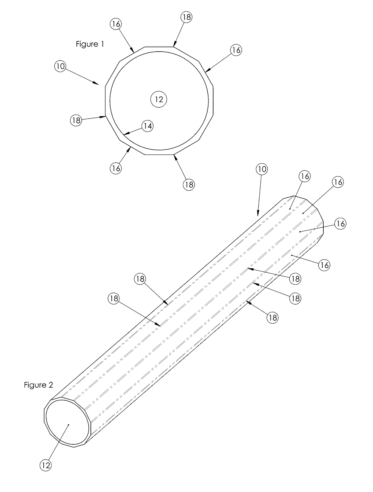
[0033]FIG. 1 discloses a tubular member 10 which serves as the handrail on a watercraft. The tubular member 10 has a hollow interior 12 and a cylindrical interior surface 14. The exterior surface has a plurality of essentially identical surfaces or facets 16.

[0034]In the embodiment shown in FIGS. 1 and 2, the tubular member has 12 facets, each of which is disposed 30° from the adjacent facets. The edges 18 of each facet 16 abut the edges of the adjacent facets and each facet runs the length of tubular member 10. The edges 18 are all parallel to the longitudinal center line of tubular member 10.

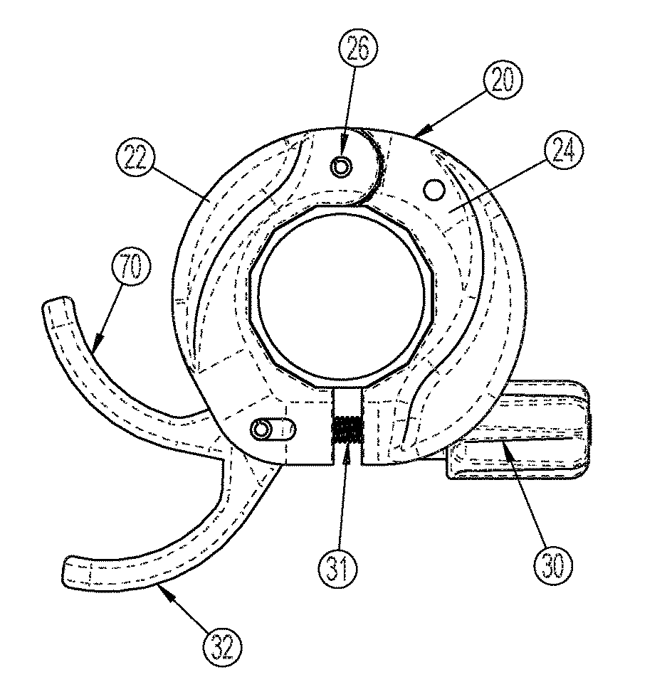
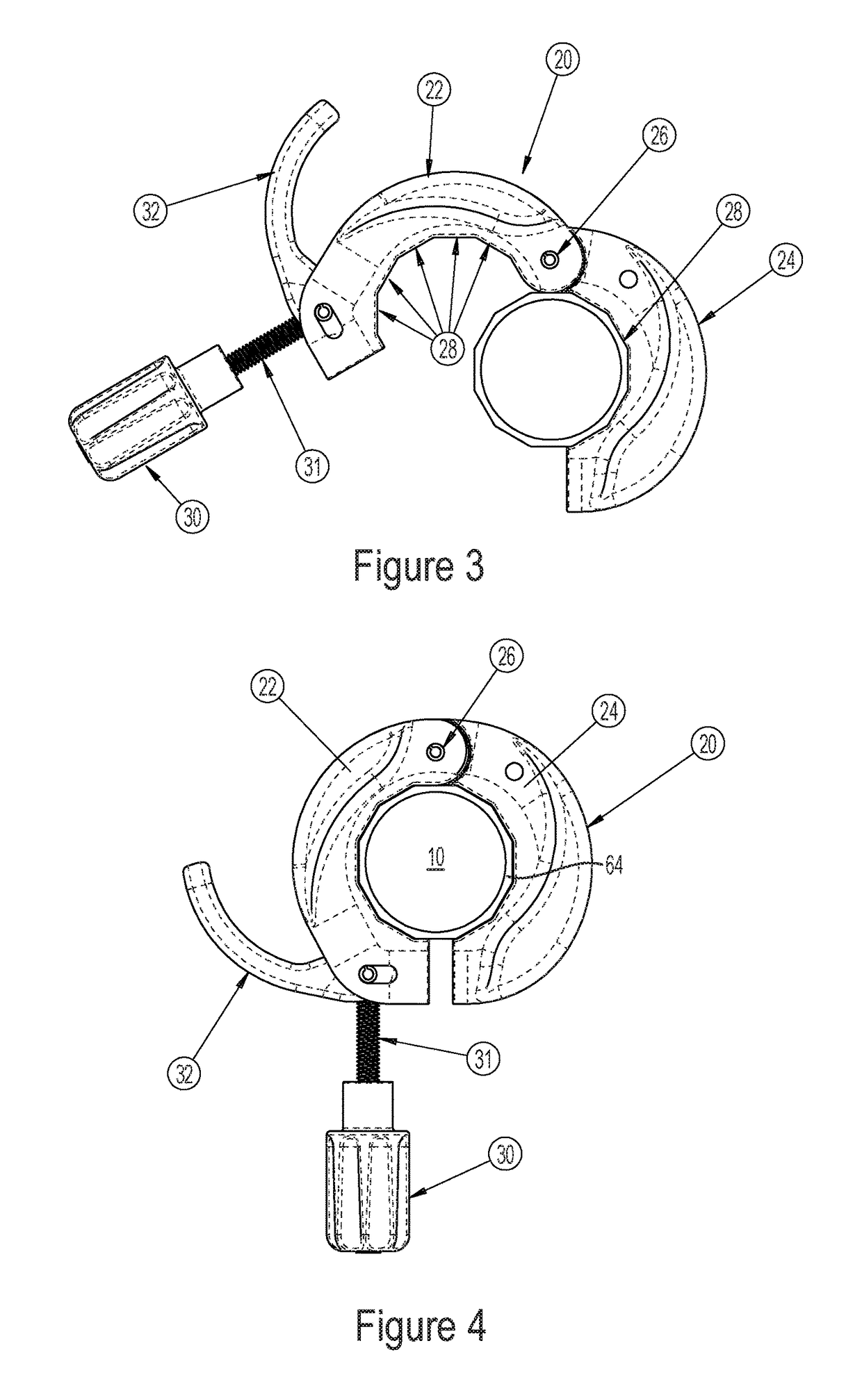
[0035]A preferred embodiment of the clamping system, generally 20, is shown in FIGS. 3 to 8.

[0036]In this embodiment, the clamp comprises two arcuate elements 22 and 24 joined by hinge 26. The inner surfaces of the arcuate elements 22 and 24 have a series of flat surfaces or facets 28 which abut the flat facets 16 on the tubular member 10 so that...


PUM


Abstract

The invention relates to a watercraft mounting system that embodies a multi-faceted tube and a mating clamp system adapted to carry an accessory. The designs of the railing and clamp have geometry to prevent rotation while allowing flexibility of adjustment in multiple positions.

Description

[0001]Applicant claims the benefit of U.S. Provisional Patent Application Ser. No. 62 / 020,045, filed Jul. 2, 2014.FIELD OF INVENTION[0002]This invention relates to systems for carrying or mounting accessories on watercraft.BACKGROUND OF INVENTION[0003]It is known to have side or transverse rails on watercraft such as canoes, kayaks, sailboats, powerboats and the like to which are mounted various common accessories, viz., fishing rod holders, cup holders, tackle or bait boxes, and the like. The side rails typically run fore to aft adjacent the cockpit and usually beyond for a substantial length of the watercraft. The rails serve as handles and take the form of hollow metal tubes which are generally cylindrical although the tubes can be solid and made of steel or any other suitable material.[0004]Mengo, U.S. Pat. No. 4,852,291 shows a fishing rod holder system for adapting a fishing rod holder to a round or four-sided square side rail. The patent does not address the adjustment of the...

Claims


Application Information

Patent Timeline
Patent Type & Authority Patents(United States)
IPC IPC(8): B63B17/00B63B25/00A01K97/10B63B17/04
CPCB63B17/04A01K97/10B63B25/002F16B2/185B63B2017/0054
Inventor KARDAS, JASON CHRISTOPHERKETTERMAN, GREGORY SCOTTDOW, PHILIP JAMESCZARNOWSKI, JAMES TAYLORBRACKETT, DREW WILLIAM
Owner HOBIE CAT IP LLC
Why Eureka
Try Eureka