Kind of pulse width dimming control circuit for LED phase cut dimming power supply

a control circuit and power supply technology, applied in the direction of electroluminescent light sources, semiconductor lamp usage, electric lighting sources, etc., can solve the problems of signal voltage distortion, poor dimming effect, narrow dimming range and other shortcomings, etc., to eliminate signal distortion, dimming light is more gentle, and the effect of strong compatibility

Active Publication Date: 2017-03-28
ZHUHAI SHENGCHANG ELECTRONICS CO LTD
View PDF1 Cites 11 Cited by
  • Summary
  • Abstract
  • Description
  • Claims
  • Application Information

AI Technical Summary

Benefits of technology

are: the Invention comprises LED phase cut dimming power supply circuit and pulse width dimming control circuit. The pulse width dimming control circuit is composed of voltage sampling amplification circuit, signal conversion circuit, photoelectric coupler and pulse width (PWM) control circuit, which are made with electric connection in turn and connected to the corresponding LED phase cut dimming power supply circuit. The LED phase cut dimming power supply circuit is composed of anti-interference circuit, main supply input live line terminal, null line terminal, power supply terminal I, power supply terminal II, circuit public terminal I and circuit public terminal II. The signal input terminal of the voltage sampling amplification circuit is connected to the main supply input live line terminal and null line terminator to the LED phase cut dimming main power supply input live line L and the null line N after passing through the anti-interference circuit for voltage sampling. The output control part of the pulse width PWM control circuit consists of a field-effect transistor, the drain electrode of which connects to LED lamp, while the source electrode of which connects to the circuit public terminal II. The voltage sampling amplification circuit collects AC voltage signal at the primary main supply input, terminal of LED phase cut dimming power supply and converts it into DC voltage signal by decompression filter. The DC voltage signal is amplified through the comparing amplifier integrated chip and its peripheral components. And then the amplified DC voltage signal is converted into the pulse width (PWM) signal through the comparator integrated chip and its peripheral components in the signal conversion circuit. And the pulse width (PWM) signal is transmitted to the pulse width (PWM) control circuit through the photoelectric coupling integrated chip. The pulse width (PWM) signal is used to control the field-effect transistor. The output anode of LED phase cut dimming power supply passes through the external LED lamp and the field-effect transistor and then returns to the output cathode AGND. Therefore, the lighting intensity of LED lamp changes with the change of the pulse width (PWM) signal imposed to the grid electrode of the field-effect transistor, thereby achieving the dimming effect. The Invention converts the voltage signal obtained by the primary sampling and amplification of LED phase cut dimming power supply into the pulse width (PWM) signal at the primary side and then transmits it through the photoelectric coupler to the pulse width (PWM) control circuit to control the lighting intensity of the LED lamp connecting to the output terminal of LED phase cut dimming power supply. Therefore, it eliminates the signal distortion caused by the optocoupler temperature drift. Moreover, the pulse width (PWM) signal converted with the use of the signal conversion circuit, which is composed of the comparator or the amplifier, does not have levels, making the dimming light more gentle. Therefore, the Invention is a kind of LED phase cut dimming power supply, which has no restriction on load power and has strong compatibility with the phase cut dimmer, wide dimming range, low temperature drift and good dimming effect.

Problems solved by technology

However, at present, most of LED phase cut dimming power supplies applied produce the dimming effect by reducing the output power through the adjustment of the input to restrict the power.
When the load power is lower than a certain range, the dimming effect will become poorer, and there would be poor compatibility with the phase cut dimmer, narrow dimming range and other shortcomings.
Although this method does not restrict the load power, great temperature drift of the optocoupler will result in signal voltage distortion, and the output voltage pulse width of LED phase cut dimming power supply will be affected.
So, the gentleness of the dimming effect is not good enough.
To sum up, in the existing technologies, LED phase cut dimming power supply has restriction on load power, poor compatibility with the phase cut dimmer, narrow dimming range, great temperature drift, poor dimming effect and other defects.

Method used


Image

  • Kind of pulse width dimming control circuit for LED phase cut dimming power supply
  • Kind of pulse width dimming control circuit for LED phase cut dimming power supply
  • Kind of pulse width dimming control circuit for LED phase cut dimming power supply

Examples


Embodiment Construction

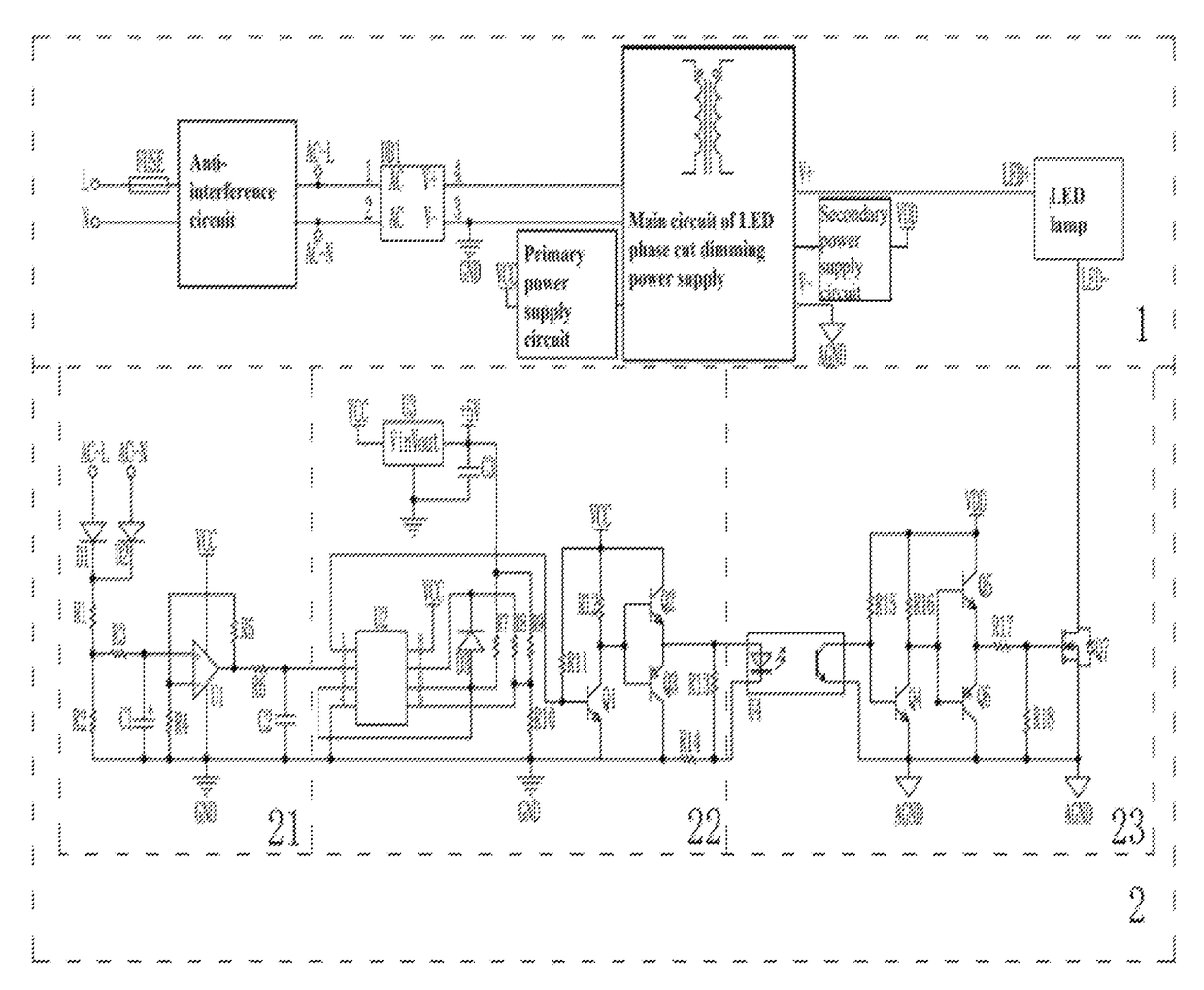
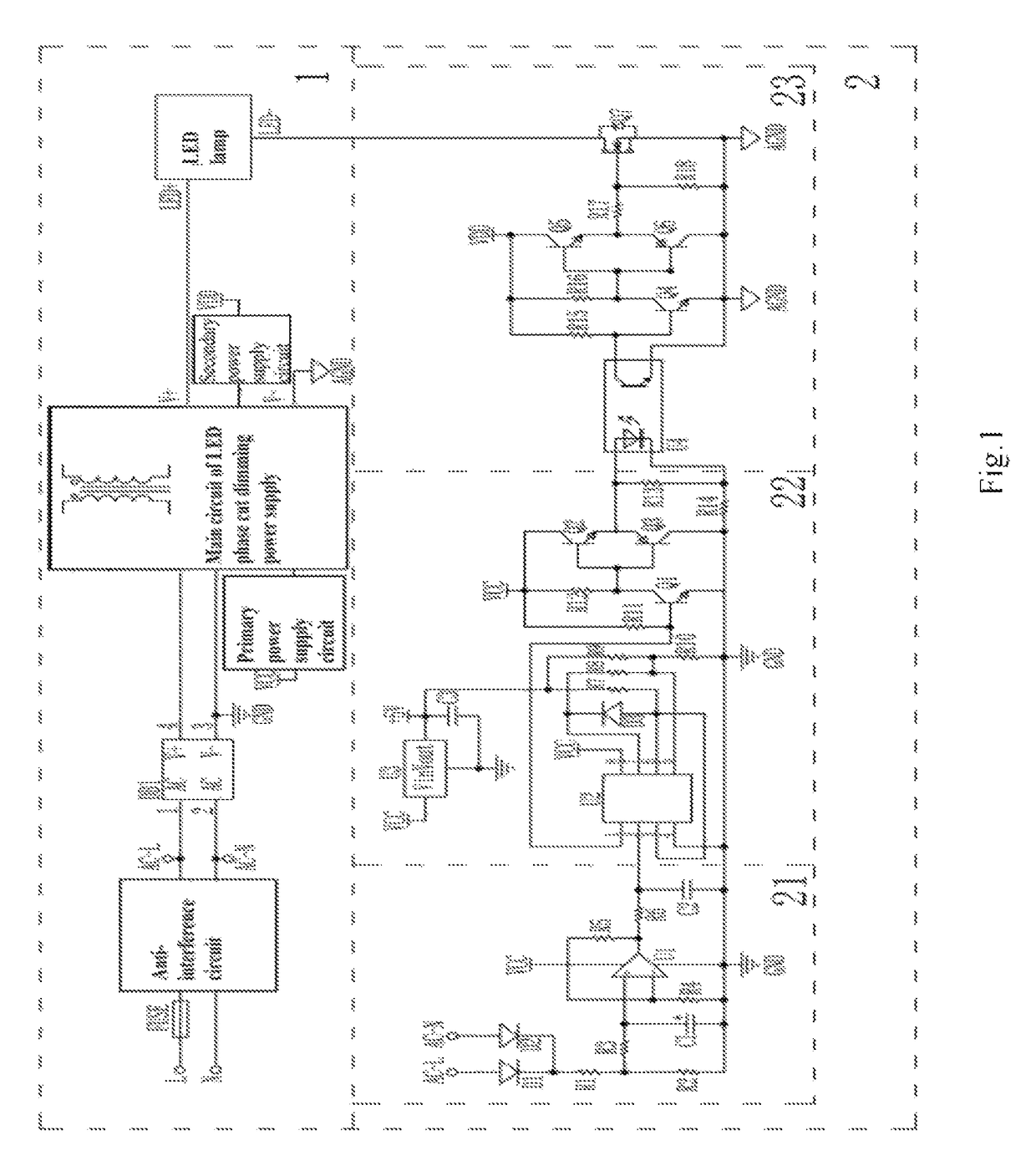
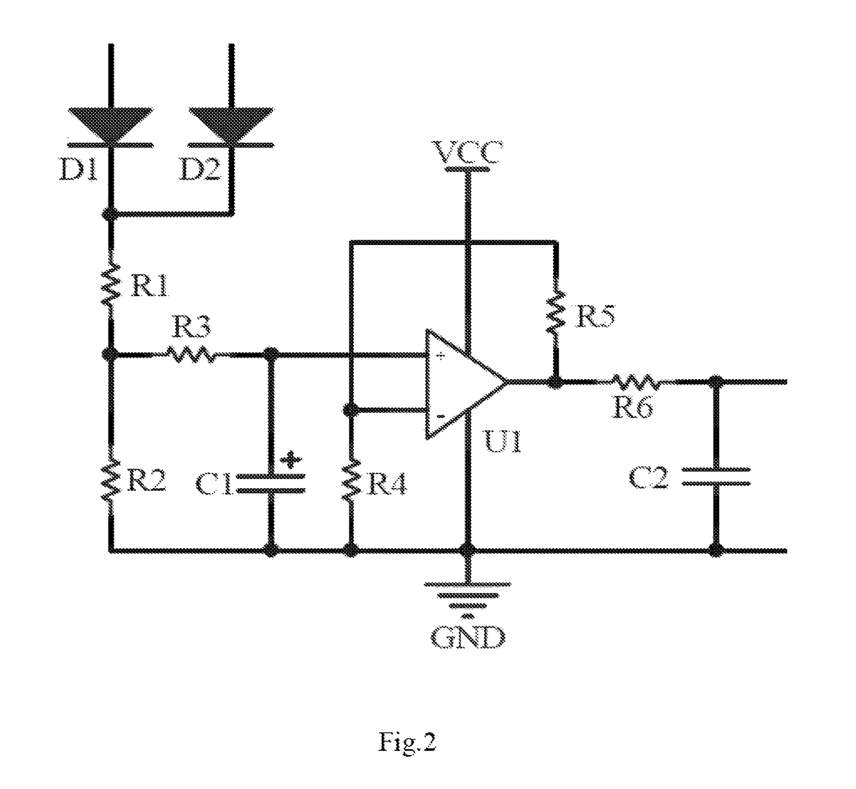
[0014]As shown in FIG. 1 to FIG. 4, the Invention comprises LED phase cut dimming power supply circuit. 1 and pulse width dimming control circuit 2. Pulse width dimming control circuit 2 is composed of voltage sampling amplification circuit 21, signal conversion circuit 22, photoelectric coupler and pulse width (PWM) control circuit 23, which are made with electric connection in turn and connected with corresponding LED phase cut dimming power supply circuit. LED phase cut dimming power supply circuit 1 is composed of anti-interference circuit, main supply input live line terminal L, null line terminal N, power supply terminal I VCC, power supply terminal II VDD, circuit public terminal I GND and circuit public terminal II AGND. The signal input terminal of voltage sampling amplification circuit 21 is connected to the main supply input live line terminal L and null line terminal N or to the LED phase cut dimming main power supply input live line AC−L and the null line AC−N after pas...


PUM


Abstract

The invention discloses a kind of pulse width dimming control circuit for LED phase cut dimming power supply, which comprises LED phase cut dimming power supply circuit and pulse width dimming control circuit. The pulse width dimming control circuit is composed of voltage sampling amplification circuit, signal conversion circuit, photoelectric coupler and pulse width PWM control circuit. The signal input terminal of the voltage sampling amplification circuit is connected to the live wire L and the null line N after passing through the anti-interference circuit for voltage sampling. The output control part of the pulse width PWM control circuit consists of a field-effect transistor, the drain electrode of which connects to LED lamp. The Invention is a kind of pulse width dimming control circuit for LED phase cut dimming power supply, which has no restriction on load power and has strong compatibility with phase cut dimmer, wide dimming range.

Description

FIELD OF THE INVENTION[0001]The Invention relates to the pulse width (PWM) dimming control circuit applied in LED phase cut dimming power supply.BACKGROUND[0002]With the development and wide application of LED illumination, LED phase cut dimming power supply is more and more widely used since it is convenient for user's installation and wire arrangement. However, at present, most of LED phase cut dimming power supplies applied produce the dimming effect by reducing the output power through the adjustment of the input to restrict the power. Such a method has a certain restriction on the load power. When the load power is lower than a certain range, the dimming effect will become poorer, and there would be poor compatibility with the phase cut dimmer, narrow dimming range and other shortcomings. Some adopt the output pulse width (PWM) dimming control circuit. However, the primary sampling signal of LED phase cut dimming power supply is transmitted to the secondary directly through the...

Claims


Application Information

Patent Timeline
Patent Type & Authority Patents(United States)
IPC IPC(8): H05B33/08H05B44/00
CPCH05B33/0845H05B33/0812H05B45/10Y02B20/30H05B45/382H05B45/395
Inventor ZHENG, DEHUAZHAO, XIANYUN
Owner ZHUHAI SHENGCHANG ELECTRONICS CO LTD
Why Eureka
Try Eureka