Method and device for checking a digital multiplier

a digital multiplier and multiplier technology, applied in error detection/correction, instruments, data conversion, etc., can solve the problems of not always recognizing false results, individual errors with multiple effects in the result word, and increasing challenges in digital electronics. achieve the effect of particularly efficien

Active Publication Date: 2017-04-04
ROBERT BOSCH GMBH
View PDF4 Cites 3 Cited by
  • Summary
  • Abstract
  • Description
  • Claims
  • Application Information

AI Technical Summary

Benefits of technology

[0018]If the error signal is determined using this example method, this then has the particular advantage that even small percentual errors in the multiplication result can be recognized.
[0020]In a particularly advantageous further aspect, the second approximated normalized mantissa is determined analogously as the approximation, limited to a second specifiable word width, of the normalized mantissa of the floating-point representation of the second factor, which also increases the efficiency of the example method. These two measures can also be combined.
[0021]In a particularly advantageous development, it is provided that the first specifiable word width is less than the word width of the first factor. This further brings about particular efficiency of the example method.
[0029]As described above, the example method according to the present invention still leaves out of consideration the sign of the first factor, or of the second factor. In a particularly advantageous development, it can be provided that a first sign of the first factor is determined and a second sign of the second factor is determined, and that a third sign of the product determined by the first multiplier unit is determined, and that it is decided that the product is incorrect if the product of the first sign and the second sign does not correspond to the third sign. In this way, the method according to the present invention can also check the sign supplied by the first multiplier unit for correctness.
[0030]Such a multiplication of the first sign and the second sign can be realized particularly efficiently by a XOR gating of the first sign and the second sign.

Problems solved by technology

Due to the increasing miniaturization of ASIC structures, and decreasing operating voltages, transient errors in digital electronics represent an increasing challenge.
A disadvantage of this method is that individual errors that have multiple effects in the result word are not always detectable.
For the securing of the multiplier, this means that false results are not recognized until they exceed or fall below a particular percent range relative to the correct result.
That is, the approximation provides a limitation of the precision of the normalized mantissa.

Method used


Image

  • Method and device for checking a digital multiplier
  • Method and device for checking a digital multiplier
  • Method and device for checking a digital multiplier

Examples


Embodiment Construction

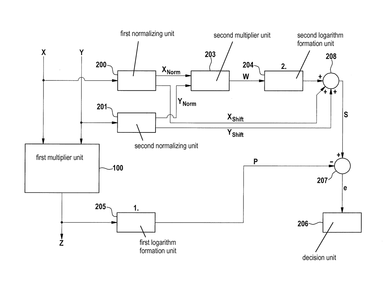
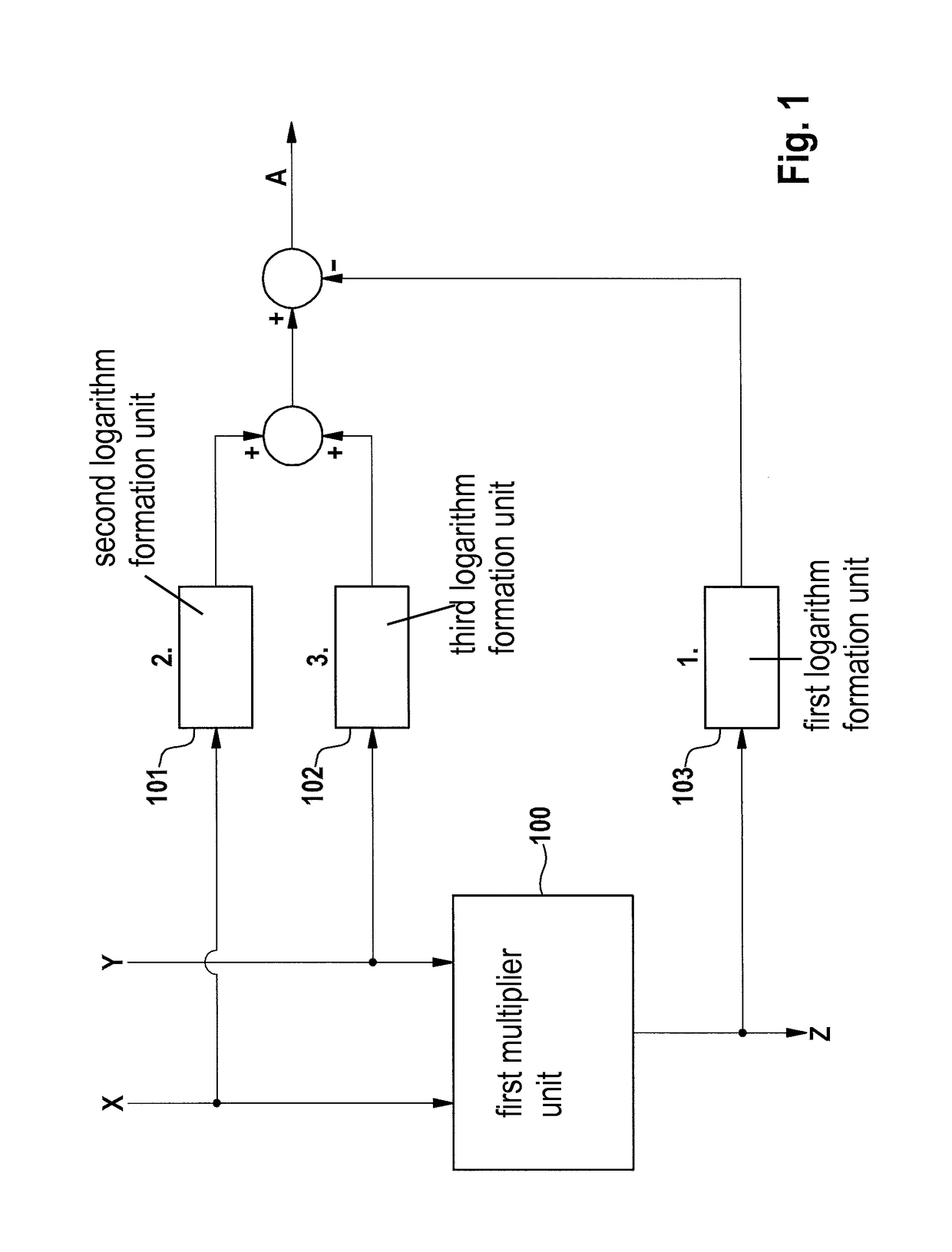
[0040]A configuration that uses equation (1) for monitoring is shown in FIG. 1. Shown is first multiplier unit 100, a first logarithm formation unit 103, a second logarithm formation unit 101, and a third logarithm formation unit 102. First factor X is supplied to second logarithm formation unit 101 and to a first input of first multiplier unit 100, and second factor Y is supplied to third logarithm formation unit 102 and to a second input of first multiplier unit 100. First multiplier unit presents at its output the product Z=X·Y of the values present at its two inputs. This product Z is supplied to first logarithm formation unit 103.

[0041]The outputs of second logarithm formation unit 101 and third logarithm formation unit 102 are added, and from them is subtracted the output of first logarithm formation unit 103, thus yielding an output signal A.

[0042]In the error-free case, and if the logarithms can be calculated approximately precisely, output signal A is approximately equal to...


PUM


Abstract

A method for calculating an error signal that enables a diagnosis of the correctness of a product, determined by a first multiplier unit, of a first factor and a second factor, the error signal being determined by a difference formation unit as the difference of a sum logarithm and a product logarithm.

Description

CROSS REFERENCE[0001]The present application claims the benefit under 35 U.S.C. §119 of German Patent Application No. DE 10 2013 202 140.2 filed on Feb. 8, 2013, which is expressly incorporated herein by reference in its entirety.BACKGROUND INFORMATION[0002]Due to the increasing miniaturization of ASIC structures, and decreasing operating voltages, transient errors in digital electronics represent an increasing challenge. For use in safety-critical systems, both transient errors and permanent errors must be recognized. Digital multipliers or squaring devices are a part of many electronic circuits and must therefore be monitored for both types of error.[0003]In order to secure multipliers or squaring units, several methods are possible. One possible design is based on redundancy: the multiplication operation is carried out multiple times (either in temporal succession or in parallel on a plurality of multiplier units), and the results are compared to one another. The hardware and tim...

Claims


Application Information

Patent Timeline
Patent Type & Authority Patents(United States)
IPC IPC(8): G06F7/487G06F11/00G06F5/01G06F11/07G06F7/523
CPCG06F5/012G06F7/4876G06F11/00G06F11/0721G06F11/0751G06F7/523G06F7/5235G06F11/0706G06F11/0754
Inventor UHL, ALEXANDER
Owner ROBERT BOSCH GMBH
Why Eureka
Try Eureka