
Loudspeaker device having foam insert to improve gas distribution in sound adsorber material

a foam insert and sound adsorption technology, which is applied in the direction of transducer details, electrical transducers, electrical apparatus, etc., can solve the problems of complex back volume shape, unacoustically desirable, and difficult to fit well into a back volume having a complex shape, so as to facilitate gas exchange and enhance the efficiency of sound adsorption material

Active Publication Date: 2017-04-04
SSI NEW MATERIAL (ZHENJIANG) CO LTD
View PDF3 Cites 10 Cited by
  • Summary
  • Abstract
  • Description
  • Claims
  • Application Information

AI Technical Summary

Benefits of technology

The invention is about an acoustic transducer device that contains a foam insert to enhance the efficiency of a sound adsorber material. The device includes an acoustic transducer, a transducer housing, and a preconfigured foam insert in the back volume of the housing. A permeable member is placed between the transducer volume and the back volume, and the foam insert and the permeable member cooperate to create a cavity within the back volume where the sound adsorber material is placed. The foam insert can have a triangular shape, a complex polygon shape, or a shape with at least one curved surface. The device also includes a charging port for the back volume. In a loudspeaker version of the device, a preconfigured foam insert is placed in the back volume and creates a cavity where a sound adsorber material is placed. The foam insert helps to exchange gas between the transducer volume and the back volume.

Problems solved by technology

A problem may arise in the insertion or placement of sound adsorber materials consisting of or at least comprising powder, loose particles, or loose grains in the back volume of the loudspeaker device.
Furthermore, the back volume of a miniature loudspeaker, such as a loudspeaker device placed in mobile phones, headsets, etc., is often constrained by other circuit components in the immediate physical area surrounding the loudspeaker, and sometimes the shape of the back volume is complex and not acoustically desirable.
A conventional technique uses tubes that encase a sound adsorber material, but these usually do not fit well into a back volume having a complex shape.
A direct insertion of the sound adsorber materials into the back volume can be practically difficult.
Furthermore, if not securely packaged, the sound adsorber materials can enter the different components of the loudspeaker device, as well as the handheld device that uses the loudspeaker device, and can therefore damage the loudspeaker device, or the handheld device that includes the loudspeaker device as a component
The packaging of a zeolite-based material for use as a sound adsorber inside the back volume of a miniature loudspeaker, such as the type usually found in today's handheld consumer electronic devices, has been challenging.
The zeolite materials disclosed in the application Ser. No. 13 / 818,374, although not electrically damaging, can interfere with the proper operation of a miniature loudspeaker, and potentially other components within a handheld consumer electronics device, if not properly contained within the device.
In addition, due to the typically limited space within the back volume portion of a miniature loudspeaker, efficient gas exchange can be impeded and the efficiency of the zeolite-based sound adsorber can be lessened by design restrictions.
Although the back volume of the miniature loudspeaker might be completely filled with a zeolite-based sound adsorber, if only a limited amount of sound adsorber surface area is exposed to pressure changes caused by acoustic transducer movement, the resonance frequency shift disclosed in application Ser. No. 13 / 818,374 is limited.

Method used


Image

  • Loudspeaker device having foam insert to improve gas distribution in sound adsorber material
  • Loudspeaker device having foam insert to improve gas distribution in sound adsorber material
  • Loudspeaker device having foam insert to improve gas distribution in sound adsorber material

Examples


first embodiment

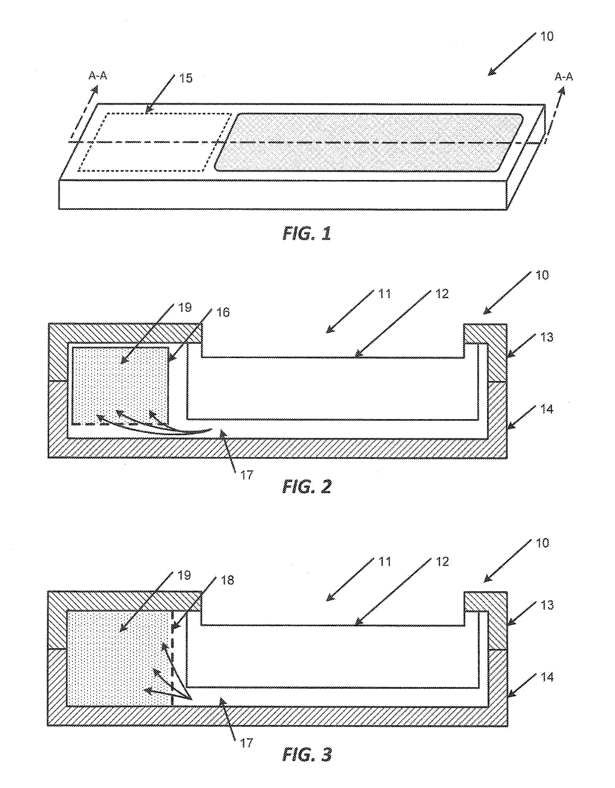
[0085]Referring to FIGS. 15A and 15B, the manufacturing method for a loudspeaker device comprising a foam channel insert and sound adsorber material will be described. At Step S100, the preconfigured foam channel insert is inserted into position in the back volume of the housing of the loudspeaker device. At this point of the assembly process, the back volume portion of the housing of the loudspeaker device is exposed to facilitate insertion of the foam channel insert. The configuration of the foam channel insert could be one of the embodiments disclosed in FIG. 5A, 6A, 7A, 8A, 9A, 10A, 11A, 11C, or 11D, or an equivalent variation. If the foam channel insert embodiment requires a permeable member, the permeable member will have already been inserted into the housing of the loudspeaker device prior to Step S100.

[0086]As Step S110, the lid is attached the rest of the housing of the loudspeaker device, thereby sealing the foam channel insert and, if required, the permeable member into ...

second embodiment

[0095]Referring to FIGS. 16A-16C, the manufacturing method for a loudspeaker device comprising a foam channel insert and sound adsorber material will be described. For this particular embodiment of the manufacturing method, back volumes that are divided in some manner or that are particularly cramped might require multiple charging ports, and thus, multiple dosing steps. At Step S300, the preconfigured foam channel insert is inserted into position in the back volume of the housing of the loudspeaker device. At this point of the assembly process, the back volume portion of the housing of the loudspeaker device is exposed to facilitate insertion of the foam channel insert. The configuration of the foam channel insert could be one of the embodiments disclosed in FIG. 5A, 6A, 7A, 8A, 9A, 10A, 11A, 11C, or 11D, or an equivalent variation. If the foam channel insert embodiment requires a permeable member, the permeable member will have already been inserted into the housing of the loudspe...


PUM


Abstract

A loudspeaker device having housing and an acoustic transducer is disclosed. The housing has a transducer space for the acoustic transducer, and a back volume space. The back volume filled with a sound adsorber material and a foam material. The sound adsorber material in the back volume space is configured to virtually increase the size of the back volume space, and shift the resonant frequency of the back volume space. The foam material facilitates gas exchange and air flow within the back volume space, and between the sound adsorber and the transducer space. The foam material is configured in different arrangements to facilitate the gas exchange and air flow.

Description

FIELD OF THE INVENTION[0001]The invention relates to the field of loudspeaker devices and, in particular, to miniature loudspeaker devices having acoustically active materials integrated within the back volume portion of the housing of the loudspeaker device.BACKGROUND OF THE INVENTION[0002]In the acoustic arts, it is conventional to place a sound adsorber material in a back volume of a loudspeaker device to acoustically enlarge the back volume in a virtual sense. In a loudspeaker device having a physically small back volume, a sound adsorber material lowers the resonance frequency of the loudspeaker device to a value that is similar to a loudspeaker device with a physically larger back volume.[0003]More specifically, sound adsorber materials disposed in the back volume of a loudspeaker device improve its sound characteristics, e.g., the wideband performance, and the apparent acoustic volume of the loudspeaker. Examples of sound adsorber materials include zeolite materials, zeolite-...

Claims


Application Information

Patent Timeline
Patent Type & Authority Patents(United States)
IPC IPC(8): H04R1/20H04R1/28
CPCH04R1/288H04R1/2811H04R2201/029H04R1/2857H04R1/2819H04R1/2853
Inventor HEROLD, JOSEFSCHMAUDER, CHRISTOPH
Owner SSI NEW MATERIAL (ZHENJIANG) CO LTD
Learn More