

Low cross-talk differential microstrip lines having slots therein of subwavelength configuration
a microstrip line and low crosstalk technology, applied in the field of transmission lines, can solve the problems of inability of those skilled in the art to use a periodical structure as a main signal transmission body, inconceivable for those skilled in the art, and inability to achieve the effect of reducing crosstalk, increasing the self-inductance of the circuit, and high current density
- Summary
- Abstract
- Description
- Claims
- Application Information
AI Technical Summary
Benefits of technology
Problems solved by technology
Method used
Image

Examples
first embodiment
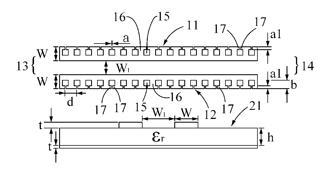
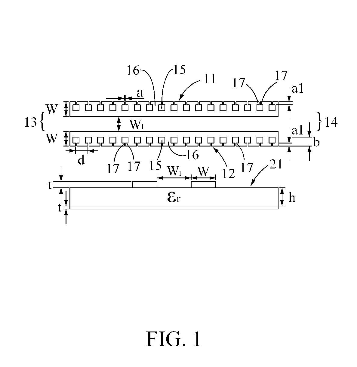
[0047]the present invention is, as shown in FIG. 1, a differential pair of microstrip lines with the opening-type periodical subwavelength configuration, wherein the differential pair is composed of two microstrip lines, the first microstrip line 11 and the second microstrip line 12, with periodical subwavelength configurations. The signals are inputted into the first terminal 13 and outputted from the second terminal 14. The signal transmitted via the first microstrip line 11 has a 180° phase difference from the signal transmitted via the second microstrip line 12 (i.e.: the signal transmitted via the first microstrip line 11 is the complementary signal of that transmitted via the second microstrip line 12.). The configuration of the slots comprises a plurality of rectangular convex bodies 16 continuously and periodically combined with a plurality of rectangular concave bodies 15. Two adjacent rectangular convex bodies 16 are divided by one rectangular concave body 15, and each of ...
second embodiment
[0053]the present invention is, as shown in FIG. 5 and FIG. 6, a differential pair with the hairpin-type periodical subwavelength configuration. As shown in FIG. 5, the differential pair is composed of two microstrip lines, the first microstrip line 11 (FIG. 5) and the second microstrip line 12 (FIG. 5), with periodical subwavelength configurations. As shown in FIG. 5, the signals are inputted into the first terminal 13 (FIG. 5) and outputted from the second terminal 14 (FIG. 5). The signal transmitted via the first microstrip line 11 has a 180° phase difference from the signal transmitted via the second microstrip line 12 (i.e.: the signal transmitted via the first microstrip line 11 is the complementary signal of that transmitted via the second microstrip line 12.). The configuration of the slots comprises a plurality of Z-shaped convex bodies 20 arranged continuously and periodically, and each of the Z-shaped convex bodies 20 comprises two extended portions 17, 18, wherein the fi...
third embodiment
[0060]the present invention is, as shown in FIG. 10, a differential pair with the slot-type periodical subwavelength configuration. The differential pair is composed of two microstrip lines, the first microstrip line 11 and the second microstrip line 12, with the slot-type periodical subwavelength configuration. The signals are inputted into the first terminal 13 and outputted from the second terminal 14. The signal transmitted via the first microstrip line 11 has a 180° phase difference from the signal transmitted via the second microstrip line 12 (i.e.: the signal transmitted via the first microstrip line 11 is the complementary signal of that transmitted via the second microstrip line 12.). The configuration of the slots comprises a plurality of rectangular convex bodies 16 continuously and periodically combined with a plurality of rectangular concave bodies 15, and the two adjacent rectangular convex bodies 16 are divided by one rectangular concave body 15, and the interval of t...
PUM
 Abstract
Description
Claims
Application Information