Stud installation and removal tool and method of use

a technology for installing and removing studs, which is applied in the direction of wrenches, screwdrivers, manufacturing tools, etc., can solve the problems of stud removal, major time-consuming and financial draining experience, and damage to the housing, so as to eliminate all side-loading, accurately torque the fastener in place, and reduce the effect of side-loading

Inactive Publication Date: 2017-04-11
HENDRIX II WILLIAM R
View PDF3 Cites 4 Cited by
  • Summary
  • Abstract
  • Description
  • Claims
  • Application Information

AI Technical Summary

Benefits of technology

[0018]The cam sleeve is machined to fit into the tool body like the teeth or cogs of a gear. Each cam sleeve can be easily removed and reinserted by aligning the teeth together. This gear-like fitting allows the cam sleeve to remain solid and act like one piece when inserted into the tool body. The cam sleeve is machined so that the back side of the jaws ride along the surface. As the jaws glide along the surface of the cam sleeve, they tighten down on the stud being removed or installed. The cam sleeve is made from hardened steel because along with the jaws, it is the piece of the tool that requires the most strength. The cam sleeves are designed to be interchangeable so that if damage occurs to the cam sleeve or the tool body, either can be replaced exclusively of the other tool parts. The cam sleeve can also be inverted so that the tool functions in both directions. This allows the tool to be used as a remover or as an installer. Because the cam sleeve can be removed and inverted to accomplish multiple operations, the inventive toot is much more versatile. Furthermore, the same tool can also be used to fit multiple sizes by changing the cage and jaws.
[0023]The inventive tool eliminates all side-loading in the removal process. Side loading occurs when lateral pressure is placed on a stud through a pulling motion. Lateral pressure at one end of the stud creates an opposite lateral pressure at the other end of the stud. This creates a mechanical bind between the stud and the housing in which it is inserted. The more exact and centered the rotation of the stud, the greater the chances of removal through rotation.
[0025]The use of the tool is generally on studs or fasteners connecting components of industrial equipment such as pumps, compressors, wind turbines, valves, etc. When used as an installer, the tool allows for increased productivity over other methods such as double nutting because the tool simply slides over a stud, grips it, and rotates it into place in the housing. Because the tool transfers 99% of the energy from the impact wrench, it can be used to accurately torque fasteners in place. The inventive tool also helps the operator distinguish between studs that can be removed through rotation and studs that may be galled, which requires a different process for removal.

Problems solved by technology

Historically in all facets of industry extracting studs, bolts and pins has been a major time-consuming and financially-draining experience for maintenance managers around the world.
A common problem resulting from the aforementioned methods, however, is that the studs will be removed with some damage to the housing, the studs, or both in most cases.
A complication of stud removal using such tools is side loading, or the mechanical binding of threaded surfaces against each other.
When side loading occurs, heat builds up due to friction between the threaded surfaces, creating a gall which is carried through the housing, tearing out the threads and impeding stud removal.
However, in the past many stud removal tools were complex, either requiring many individual pieces, or were of a design which required a considerable amount of effort and physical manipulation in removing the headless bolt from the associated mechanical device.
Furthermore, traditional stud removal tools are heavy and, thus, cumbersome to use.
Additionally, many of these tools were very expensive to manufacture because of the large number and intricacy of the individual components.
Furthermore, many of the stud removal tools were designed in such a way that they were prone to breakage and rendered useless upon the failure of any single component.
However, this method of stud removal results in damage to the stud and the fixture.
However, these devices also result in further stripping of the threads of the stud, impeding removal from the fixture.
However, this method of removal results in damage to the stud, is time consuming, involves multiple steps for stud removal, and may result in damage to the fixture.
Such devices may require a cartridge having many small parts that is used to apply torque to the damaged stud.
These multiple small parts of the cartridge, such as multiple helical springs, studs and screws holding gripping jaws together, are prone to breakage when the rotative force of an air impact tool is applied.
However, the finger splits of the housing cannot fit over multiple stud sizes, so that the tool is limited in usage.
A further complication of the cartridges and associated parts is the use of a retaining ring or clip.
The retaining ring or clip is prone to breakage, resulting in a damaged and useless tool.
Yet another complication is “chattering.” where the tool does not perfectly conform to the size of the fastener.
When rotative force is applied using an air impact tool, the removing tool “chatters” over the damaged corners of the fastener, further stripping the fastener or damaging the tool interface with the fastener, and causing ‘radii’ to form on the end of the tool.
However, regardless of the size, the prior art nonetheless results in chattering from an imperfect size conformance; thus, stripping of the thread occurs.
Further, the use of a set of tools having a multiplicity of sizes to conform to stud size presents another complication.
If there exists a multiplicity of removal tool sizes in a set, the loss of one of the tools results in a useless tool set.
Furthermore, the insertion of studs is often a difficult, tedious and very expensive task.
However, in the past many stud driving and insertion tools were complex, either requiring many individual pieces, or were of a design which required considerable amount of effort and physical manipulation in mounting the headless bolt or stud into the associated mechanical device.
Many of these tools were very expensive to manufacture because of the large number and intricacy of the individual components.

Method used


Image

  • Stud installation and removal tool and method of use
  • Stud installation and removal tool and method of use
  • Stud installation and removal tool and method of use

Examples


Embodiment Construction

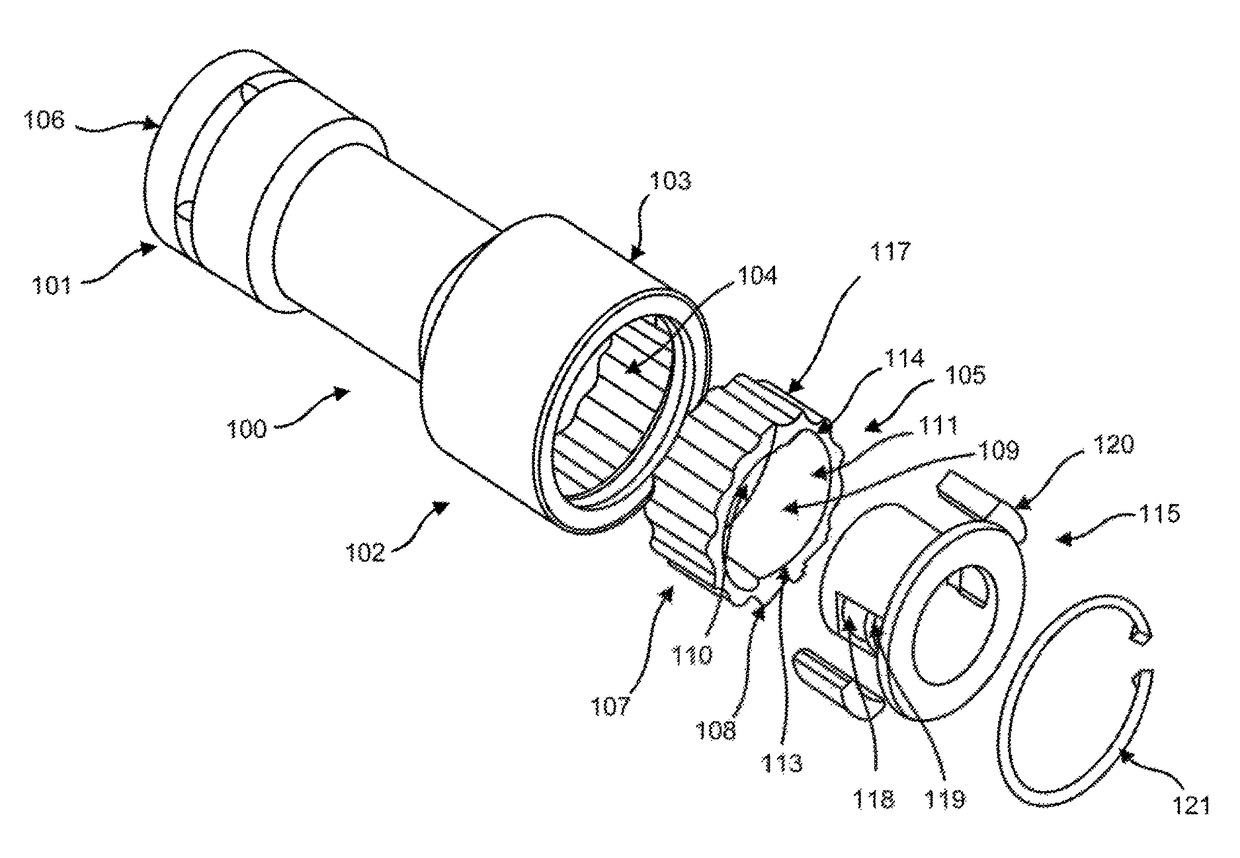
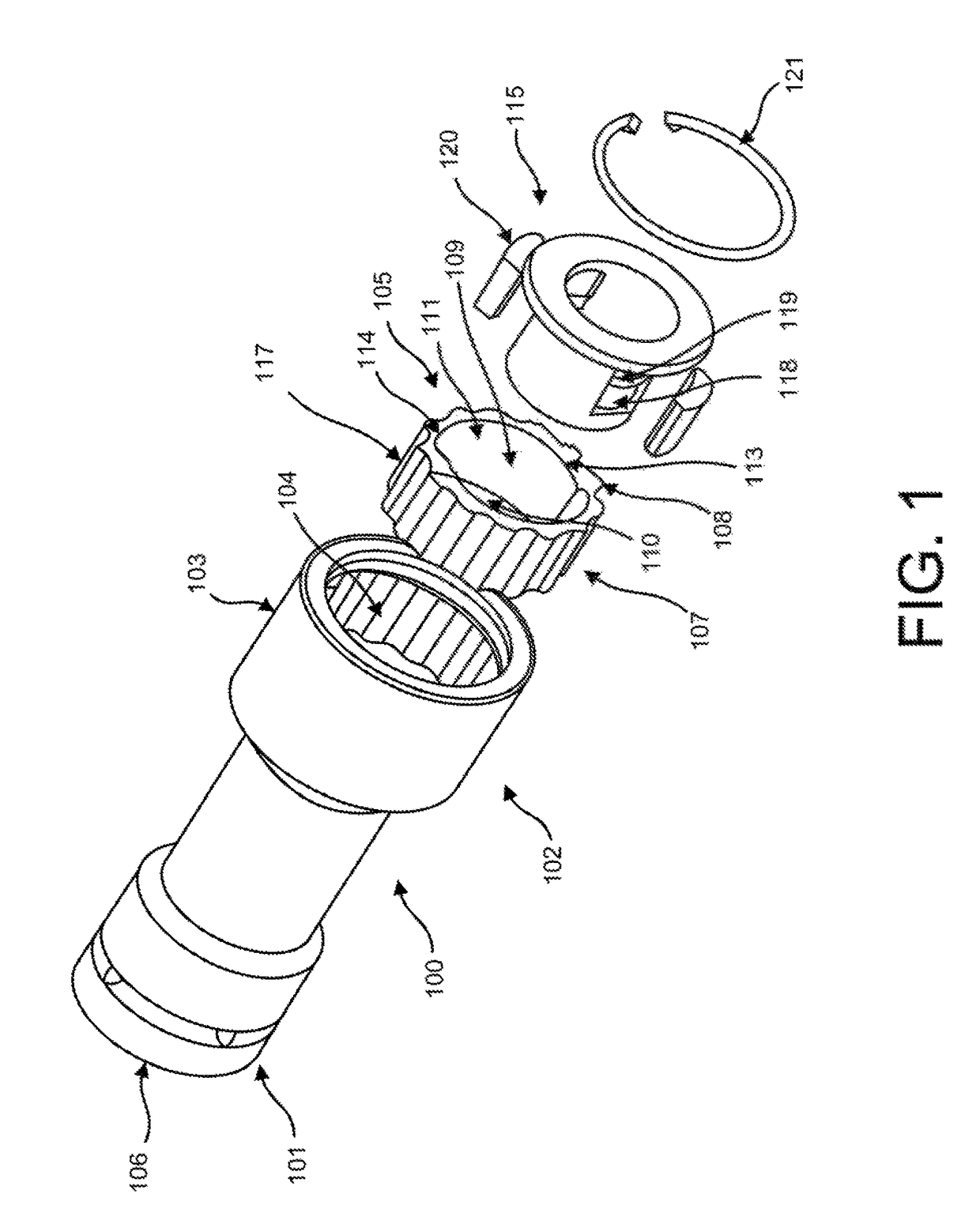
[0036]FIG. 1 of the drawings shows a preferred embodiment of the stud removal and installation tool, having a cylindrical body (100) having a first end (101) and a second end (102) with a hollow cylindrical housing (103) having a front face and side walls. The second end of the hollow interior of cylindrical housing (104) is lined with grooved teeth sized to allow cam sleeve (105) to sit flush inside cylindrical housing (101). The cam sleeve (105) is reversible such that it may be inserted into the body (100) in an orientation for installation of the threaded member or removal of the threaded member. The first end opposite end of the cylindrical body (100) is additionally hollow with a drive recess (106) formed to allow for coupling to an impact tool or driver device with which to apply rotational forces to the stud removal and installation tool. Also shown in FIG. 1 is the cam sleeve (105). The exterior surface of cam sleeve (107) is lined with teeth (108) sized to insert flush int...


PUM

PropertyMeasurementUnit
rotational forceaaaaaaaaaa
sizesaaaaaaaaaa
temperaturesaaaaaaaaaa

Abstract

An inventive stud removal and installation tool and method of use is disclosed. The inventive tool incorporates a body configured to hold a cage, cam sleeve and jaws. The cam sleeve is capable of being oriented to accomplish either stud removal or installation. The assembly of the tool is modular such that broken elements can be replaced without the need to replace the entirety of the tool.

Description

FIELD OF THE INVENTION[0001]The present invention relates to a tool for installing and removing nuts, bolts and / or studs from a work piece. The invention may be used with nuts, bolts and / or studs of various sizes. The present invention further encompasses a lightweight tool with modular and interchange parts.BACKGROUND OF THE INVENTION[0002]Studs, threaded bolts or pins are commonly used in industrial applications to fasten equipment together or to fasten objects to some type of foundation. Over time, these studs can become frozen through the process of varying temperatures or exposure to elements. Threaded bolts can become frozen and have the heads twisted off in the removal process, leaving the user with a stud still frozen in place. Historically in all facets of industry extracting studs, bolts and pins has been a major time-consuming and financially-draining experience for maintenance managers around the world.[0003]Oftentimes mechanics needing stud removal services will simply ...

Claims


Application Information

Patent Timeline
Patent Type & Authority Patents(United States)
IPC IPC(8): B25B27/18B25B13/18B25B23/10
CPCB25B13/18B25B23/103Y10T29/49815Y10T29/49822Y10T29/49826Y10T29/49947Y10T29/53417Y10T29/53596
Inventor HENDRIX, II, WILLIAM R.
Owner HENDRIX II WILLIAM R
Why Eureka
Try Eureka