
Vehicle

a technology for vehicles and rear wheels, applied in the field of vehicles, can solve the problems of the difference in the driving force between the left and the right rear wheels, and achieve the effects of preventing the support member of the wheel, facilitating the operation of each wheel, and facilitating the movement of the wheel

Active Publication Date: 2017-04-11
SEARCHWARE
View PDF36 Cites 7 Cited by
  • Summary
  • Abstract
  • Description
  • Claims
  • Application Information

AI Technical Summary

Benefits of technology

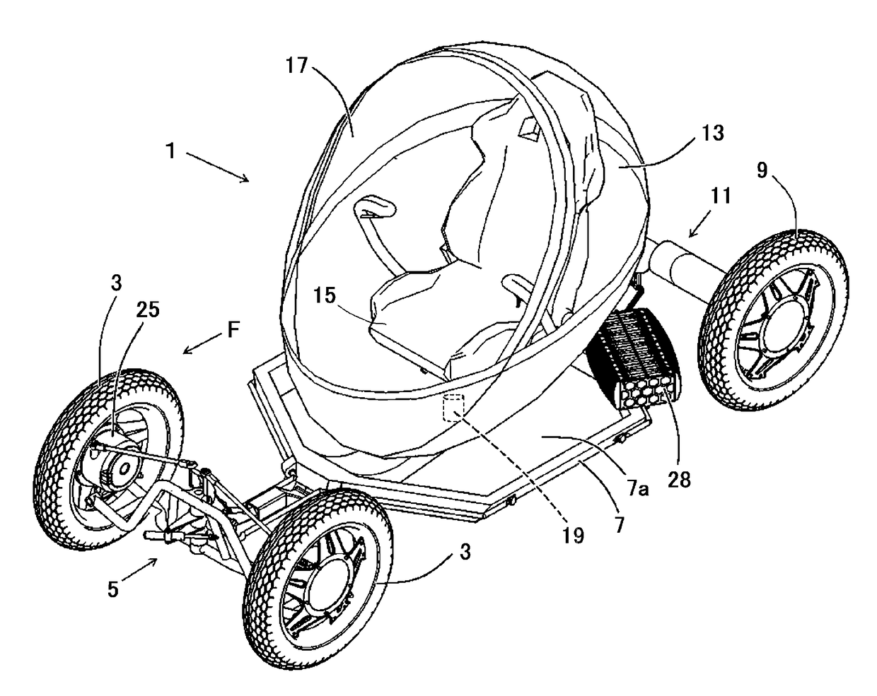
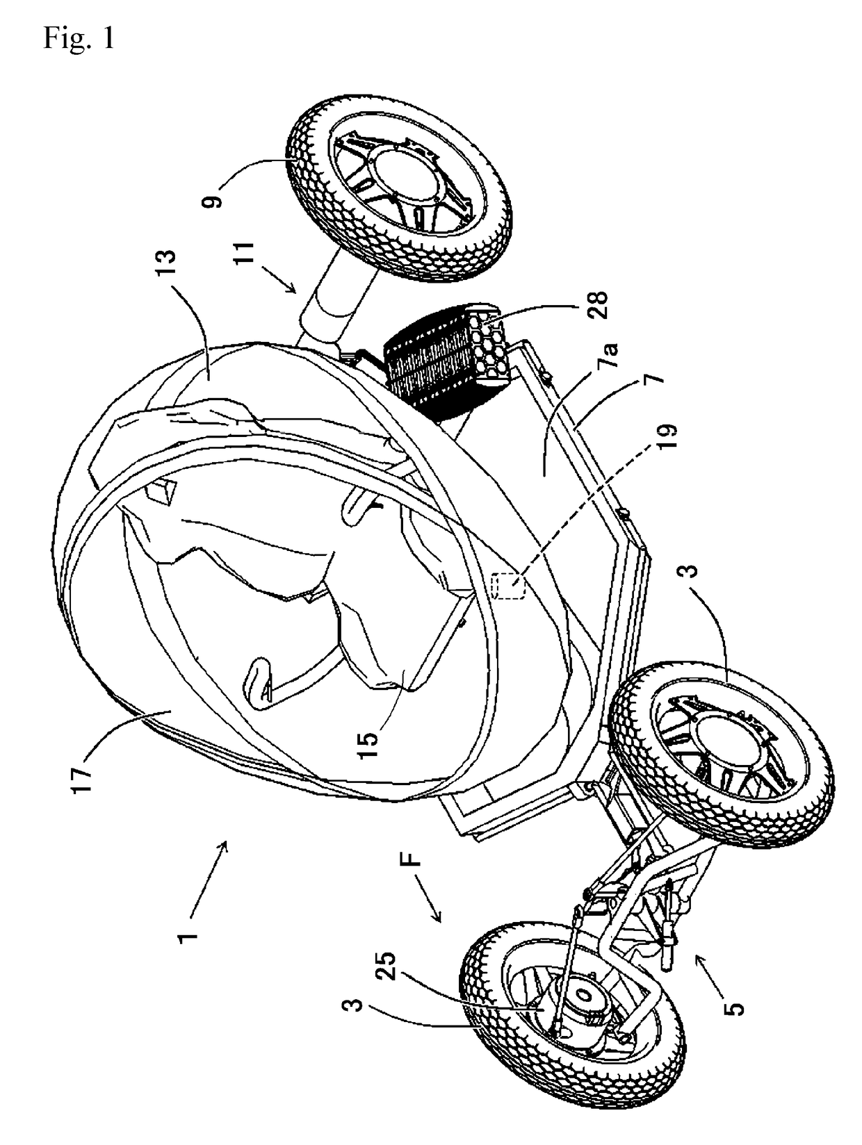
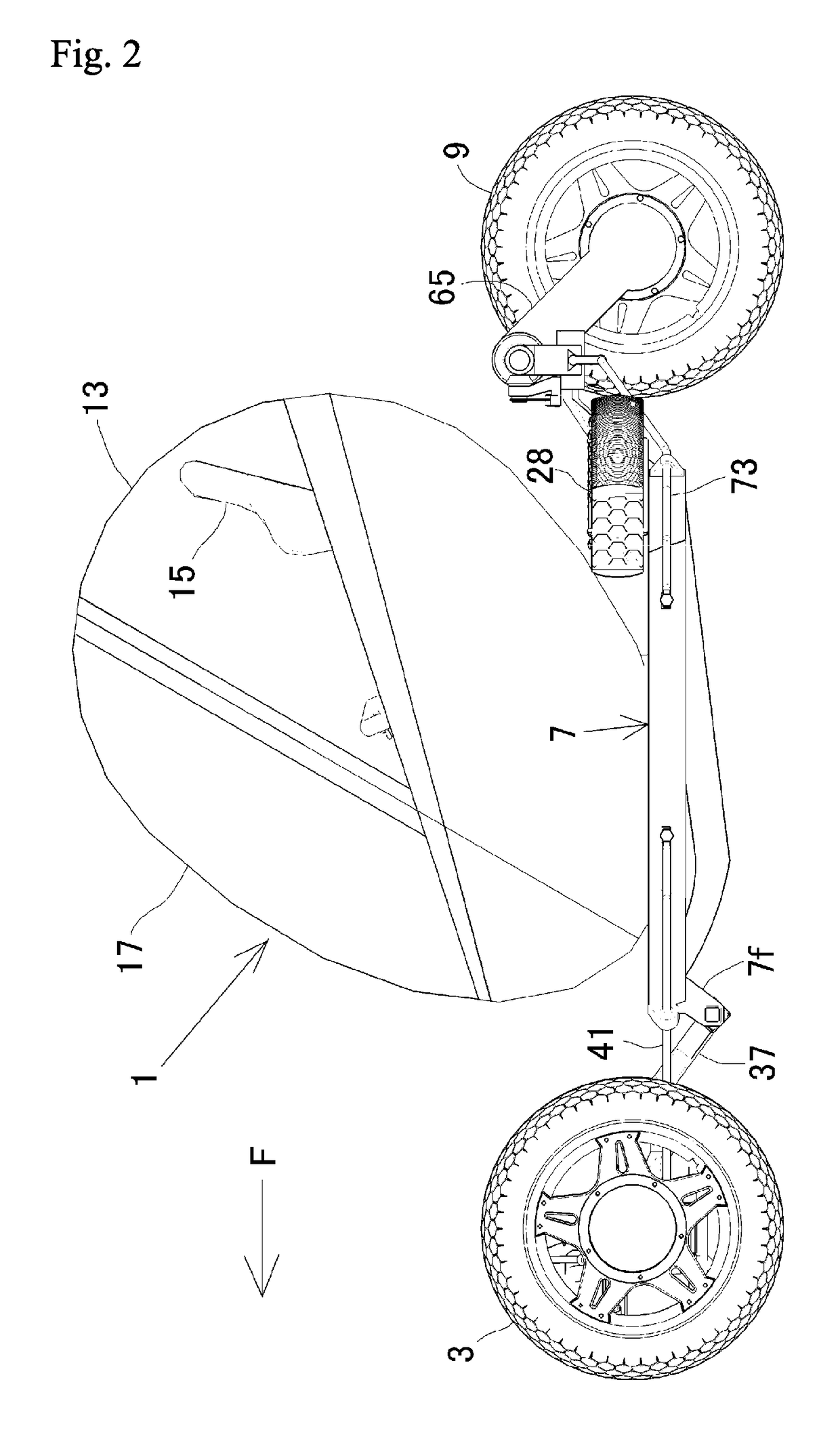
[0040]According to the first aspect, the difference in torque between the wheels causes the wheel support member to rotate with respect to the base member. Accordingly, each wheel is steered and the vehicle is turned, and, at the same time, the wheels are interlocked and displaced relatively to one another vertically in opposite directions with respect to the vehicle body. Also, the vehicle body is tilted inwardly in the turning direction. Thus, two motions including the relative displacement and the steering can be simultaneously and easily performed on each wheel. In addition, the vehicle includes the linkage mechanism that can mechanically interlock the wheels by means of the wheel support member and can relatively displace the wheels vertically in opposite directions with respect to the vehicle body. Also, by mechanically interlocking the wheel support member with the base member and by allowing rotation of the wheel support member about the steering axis, the wheels are displaced relatively to one another vertically in opposite directions with respect to the vehicle body. Hence, both the wheels can be reliably displaced to one another vertically in opposite directions and only one wheel cannot be disproportionately displaced.
[0041]Further, because the wheels are interlocked and displaced relatively to one another vertically in opposite directions with respect to the vehicle body, the vehicle body is tilted inwardly in the turning direction. Hence, the vehicle's turning ability becomes better.
[0042]Furthermore, the wheel support member is rotatably supported by the base member about the steering axis that is inclined such that an upper portion thereof is positioned forwardly of a lower portion thereof. Accordingly, the difference in torque given to each wheel causes the wheel support member to rotate with respect to the base member, so that the wheels can be easily displaced vertically in opposite directions. Moreover, the steering axis, which is the rotation pivot of the wheel support member, is inclined forwardly. Accordingly, when the wheel support member rotates in the vehicle turning direction, the wheels are steered, so that not only the wheels are directed in the vehicle turning direction, but also the vehicle body is tilted inwardly in the turning direction. Hence, the vehicle's turning ability becomes better.
[0043]According to the second aspect, the base member that supports the wheel support member is supported via the elastic member by the vehicle body. Thus, road surface roughness-derived vibrations that spread from the wheels via the wheel support member to the base member can be prevented from further spreading to the vehicle body.
[0044]According to the third aspect, the vehicle includes the resistance means for resisting the rotation of the wheel support member when the wheel support member rotates. Thus, it is possible to prevent the wheel support member from rotating abruptly.
[0045]According to the fourth aspect, the battery is supported by the vehicle body such that the center of gravity of the battery is positioned lower than the tilting center when the vehicle body is tilted in a vehicle widthwise direction. This can prevent the vehicle body from being tilted outwardly in the turning direction due to centrifugal force imposed on the battery when the vehicle turns.

Problems solved by technology

This causes a difference in the driving force between the left and the right rear wheels.

Method used


Image

  • Vehicle
  • Vehicle
  • Vehicle

Examples


first modification embodiment

[0244]The previous Embodiment illustrates an example in which an occupant on the vehicle 1 operates the brake operator 21 and the acceleration operator 22 installed on the steering yoke 20 and manually drives the vehicle 1. However, like the first Modification Embodiment as illustrated in FIGS. 26 to 30, the automatic driving mode in which neither the steering yoke 20, the brake operator 21, nor the acceleration operator 22 of the vehicle 1 is manipulated may be optionally switched to and from the above manual driving mode.

[0245]In this Modification Embodiment, the vehicle 1 carries various on-vehicle devices including: a switching unit 130 for switching between the manual driving mode and the automatic driving mode; an imaging unit 131 for imaging the traveling direction of the vehicle 1; a map information storage unit 133 for storing road map information; a travel route control unit 135 for guiding the vehicle through a travel route to a destination after the destination has been ...

second modification embodiment

[0268]The previous Embodiment and the first Modification Embodiment illustrate an example configuration in which the pair of left and right wheel holding members (65 and 65) are interlocked to one another and moved vertically in opposite directions while the intermediate bevel gear 87 is engaged with the pair of main bevel gears (83 and 83). However, in the second Modification Embodiment shown in FIG. 31, it is possible that the pair of left and right wheel holding members (65 and 65) are interlocked to one another and moved vertically in opposite directions by means of a link mechanism.

[0269]In this Modification Embodiment, one end portion of a link member 119 is pivotally connected using a first universal joint 117 to a longitudinal intermediate portion of the wheel holding member 65. The other end portion of the link member 119 is pivotally connected via a second universal joint 121 to an end portion of a V-shaped rocking arm 123. A center portion of the V-shaped rocking arm 123 ...

third modification embodiment

[0272]The previous Embodiment and the first Modification Embodiment illustrate an example configuration in which by changing the length of the electric actuator 57, the front-to-rear tilt angle of the virtual straight line Lf along the axis of the steering shaft member 51 is altered. In the third Modification Embodiment shown in FIG. 32, the vehicle height on the front wheel 3 side of the vehicle 1 may be shifted during acceleration and deceleration, the shift depending on whether the vehicle 1 is under a running state or a stopped state. This may be used to alter the front-to-rear tilt angle of the virtual straight line Lf.

[0273]In this Modification Embodiment, a front end portion of a long arm part 631b is attached to a longitudinal intermediate and rear portion of the first center support member main body 631a, which corresponds to the first center support member main body 31a according to the previous Embodiment. The first center support member main body 631a and the arm part 63...


PUM


Abstract

Provided is a vehicle which, when a pair of left and right wheels are displaced with respect to the vehicle body due to the difference in drive force between the wheels, the two wheels are reliably displaced vertically in opposite directions such that neither wheel is disproportionately displaced and such that both wheels are steered during said displacement of both wheels vertically in opposite directions. An electric motor applies drive torque to the front wheels individually. A vehicle body frame supports the front wheel support member to allow rotation about a forwardly inclined steering axis (Lf). By allowing rotation of the front wheel support member about the steering axis (Lf), the front wheels are displaced relatively to one another vertically in opposite directions with respect to the vehicle body frame and the front wheels are steered.

Description

TECHNICAL FIELD[0001]The present invention relates to a vehicle in which a vehicle body can be made to be tilted and wheels can be steered during turning, and to a vehicle having a pair of left and right wheels and capable of having a simplified coupling structure between the wheels and a vehicle body.BACKGROUND ART[0002]A conventional vehicle shown in Patent Literature 1 has a pair of left and right rear arms suspended via a shock absorber on a vehicle body, with one end portion of each rear arm being used to support a rear wheel and the other end portion of each rear arm being coupled to the vehicle body. The one end portion of each rear arm can be individually moved in a vertical direction. When the vehicle turns, the outside rear wheel with respect to the turning direction is given larger driving force than the inside rear wheel. This causes a difference in the driving force between the left and the right rear wheels. This difference makes the rear arm on the outer side with res...

Claims


Application Information

Patent Timeline
Patent Type & Authority Patents(United States)
IPC IPC(8): B60K1/00B62D9/02B60G3/26B62D9/04B62D9/00B60L15/20B60L11/18B60L7/12B62K21/00B62D11/20B62K5/01B60G3/14
CPCB62D9/02B60G3/145B60G3/26B60L7/12B60L11/1864B60L11/1877B60L11/1879B60L15/2009B60L15/2036B62D9/002B62D9/04B62D11/20B62K5/01B62K21/00B60G2200/46B60G2300/13B60G2300/45B60L2210/10B60L2220/44B60L2220/46B60L2240/12B60L2240/421B60L2240/423B60L2250/24B60L2270/145Y02T10/645Y02T10/7005Y02T10/7061Y02T10/7216Y02T10/7275B60L58/21B60L50/66B60L50/64Y02T10/64Y02T10/70Y02T10/72
Inventor SUZUKI, MASANOBU
Owner SEARCHWARE
Learn More