Electro control hazing device (ECHD)
a technology of electronic control and hazing device, which is applied in the direction of weapons, weapons types, etc., can solve the problems of requiring maintenance, electrical fence system installation of physical structure, and only conditioned targets,
- Summary
- Abstract
- Description
- Claims
- Application Information
AI Technical Summary
Benefits of technology
Problems solved by technology
Method used
Image
Examples
first embodiment
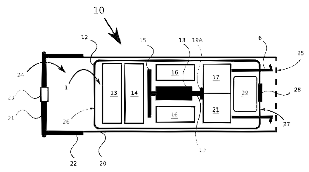
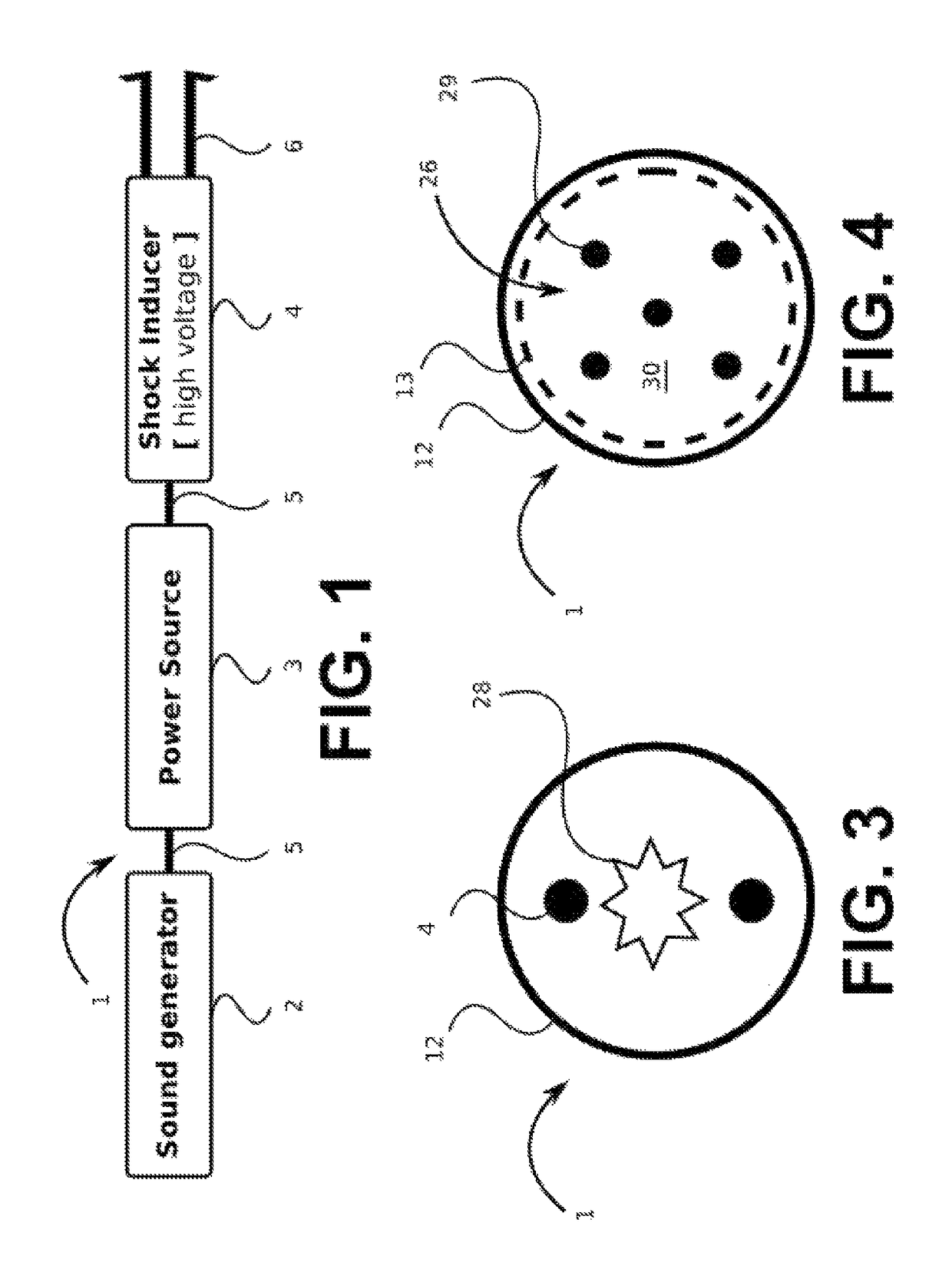
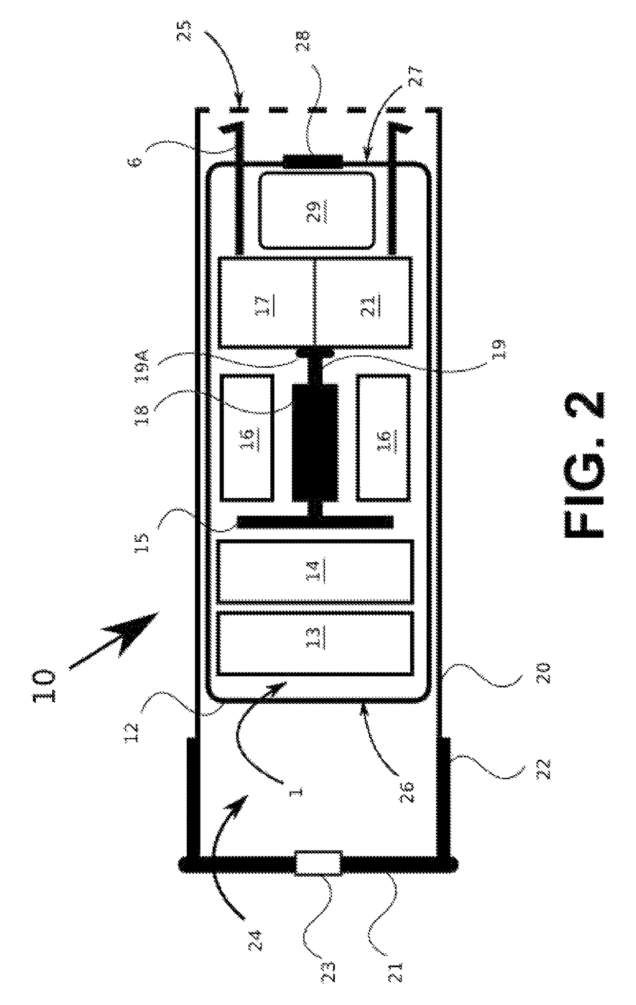
[0076]FIG. 2 illustrates a cross sectional view of a device first shown in FIG. 1 where the power source includes use and motion of a magnet to generate power for operating at least some of the components of the device. With reference to FIG. 2, a device 1 is placed inside a shotgun shell 10. The shotgun shell 10 includes a generally metal endplate 21, a metal sidewall 22 and a sidewall 20 which may be made from a plastic, metal, polymer, glass or other material. The distal end 25 of the shell 10 may be enclosed with wrappings of the sidewall 20 or may be open depending on the needs or configuration of the device 1. The end plate 21 is loaded with a primer 23 that may serve as propellant. Additionally, The endplate 21, metal sidewall 22 and sidewall 20 enclose a space 24 that may house a propellant (not shown) such as a combustible material such as gunpowder or the like for projecting the device 1 from the distal end 25 of the shell 10.
[0077]The device 1 includes a housing 12 having...
second embodiment
[0088]FIG. 5 illustrates a cross sectional side view of a device first shown in FIG. 1 where the power source includes use and motion of a piezoelectric film. With reference to FIG. 5, the device 1 includes a housing 12 having a proximal end 26 and a distal end 27. The housing 12 encloses other components of the device 1. The device 1 includes a sound generator 13 which in turn includes a speaker. The sound generator 13 is powered by a power source. The sound generator 13 is recordable for approximately 6-15 seconds. The sound may be an animal, human or siren-type noise. The message repeats as long as power is available. The sound generator 13 is electronically connected with circuitry 14 and a power source which includes various components in the device 1. The circuitry 14 may include controlling elements that direct actuation of the other elements in the device 1 such as the sound generator 13 or electrodes 4 for delivering conditioning shocks. According to a variation, the circui...
third embodiment
[0094]FIG. 6 illustrates a cross sectional side view of a device first shown in FIG. 1 where the power source includes use of a battery or stored source of power. With reference to FIG. 6, the device 1 includes a housing 12 having a proximal end 26 and a distal end 27. The housing 12 encloses other components of the device 1. The device 1 includes a sound generator 13 which in turn includes a speaker. The sound generator 13 is powered by a power source. The sound generator 13 is recordable for approximately 6-15 seconds. The sound may be an animal, human or siren-type noise. The message repeats as long as power is available. The sound generator 13 is electronically connected with circuitry 14 and components collectively referred to as element 36. Element 36 includes various components including a battery, control board with a micro sound chip, timer circuitry and an impact trigger or sensor. Leads and wires between various components of the device 1 are not shown in FIG. 6 for sake ...
PUM
 Abstract
Description
Claims
Application Information
 - R&D
- Intellectual Property
- Life Sciences
- Materials
- Tech Scout
- Unparalleled Data Quality
- Higher Quality Content
- 60% Fewer Hallucinations
Browse by: Latest US Patents, China's latest patents, Technical Efficacy Thesaurus, Application Domain, Technology Topic, Popular Technical Reports.
© 2025 PatSnap. All rights reserved.Legal|Privacy policy|Modern Slavery Act Transparency Statement|Sitemap|About US| Contact US: help@patsnap.com


